CMMT-AS Servo Drive with 3rd Party Linear Motor
Paul Obie, Application Engineer, Festo USA
Shane Roy, Mechatronics Application Engineer, Festo USA
Introduction
CMMT-AS drives are typically configured for Festo’s existing motor catalog, which includes all rotary servo motors. As a result, there is no built-in template for a third-party linear servo. The linear axes offered by Festo are essentially rotary servos mechanically coupled to either a ball screw or toothed belt axis. Unlike a rotary servo, which is self-contained, a linear servo typically consists of a static strip of permanent magnets (the stator), with an electromagnet (the rotor) mounted separately on an axis. To enable closed-loop control, an external encoder is used to track the rotor’s position.
When connecting a linear servo motor to a CMMT-AS drive, the parameters that define the linear servo must be translated into those of a rotary servo. Once these parameters are correctly set, the motor can be tuned. It is important to note that, since the linear axis guiding the rotor across the stator is often custom-built (unless purchased as a complete system), mechanical troubleshooting is necessary to ensure minimal friction throughout the stroke of the axis.
Mechanical Troubleshooting
A servo is tuned based on the load on the axis and the friction within the system. During a single move, both the load and friction are expected to remain consistent, which forms the basis of the tuning process. While the load can be compensated by adjusting the load parameter between moves, the friction is assumed to be constant. Therefore, before commissioning
a third-party servo, it is crucial to verify that the axis moves freely and that no areas exhibit high friction. Excessive friction can prevent the drive from successfully commutating during initial startup.
Several factors can contribute to excessive friction in a linear servo, including:
- Misalignment of the guides (if multiple are used.)
- Excessive load on the guide(s), leading to failure.
- Guides being spaced too far apart.
- Insufficient rigidity of the rotor mounting.
In a linear servo, the rotor and stator are separated by a small air gap, and the system operates most efficiently with a smaller gap. During operation, the rotor is drawn toward the stator due to the magnetic field. Therefore, a system where the rotor is not mounted rigidly enough may
result in the rotor becoming stuck on the stator after the motor is activated.
Electrical Troubleshooting
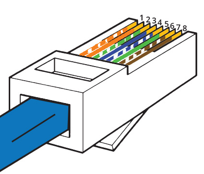
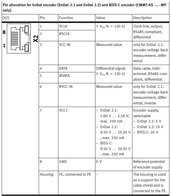
A common issue with the startup of a 3rd party motor is incorrectly wiring the encoder to the drive. Since these drives use a RJ45 connector for the encoder, the orientation of the pins is critical to proper encoder communications. In the CMMT-AS manual, the following information is provided:
This diagram is from the point of view of the port on the drive, but for wiring the encoder connector, the pins need to be oriented in this direction:

Parameter Configuration
From an example application, refer to the following components for the system:
- Festo CMMT-AS-C5-11A-P3-MP-S1 (Servo Drive).
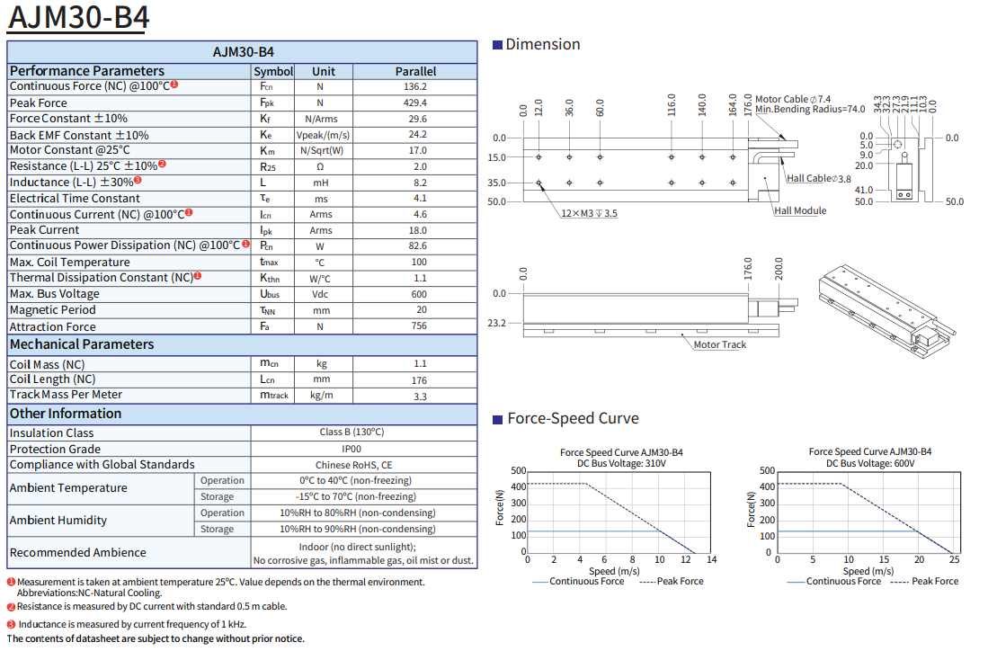
- Akribis AJM30-B4 (Linear Servo, includes the rotor and stator, 500mm total length).
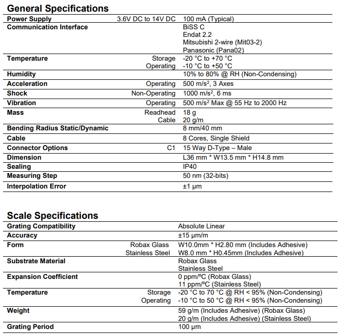
- Akribis ABA50 (Optical Absolute Linear Encoder, using Endat 2.2 communication).
The following information is provided by Akribis for the components, these specifications will be referenced in the subsequent steps:
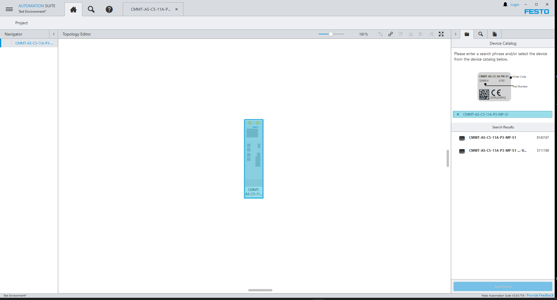
- Open Festo Automation Suite, search for the drive, drag and drop into the editor in the center, and then double-click the drive icon to open its plug-in.
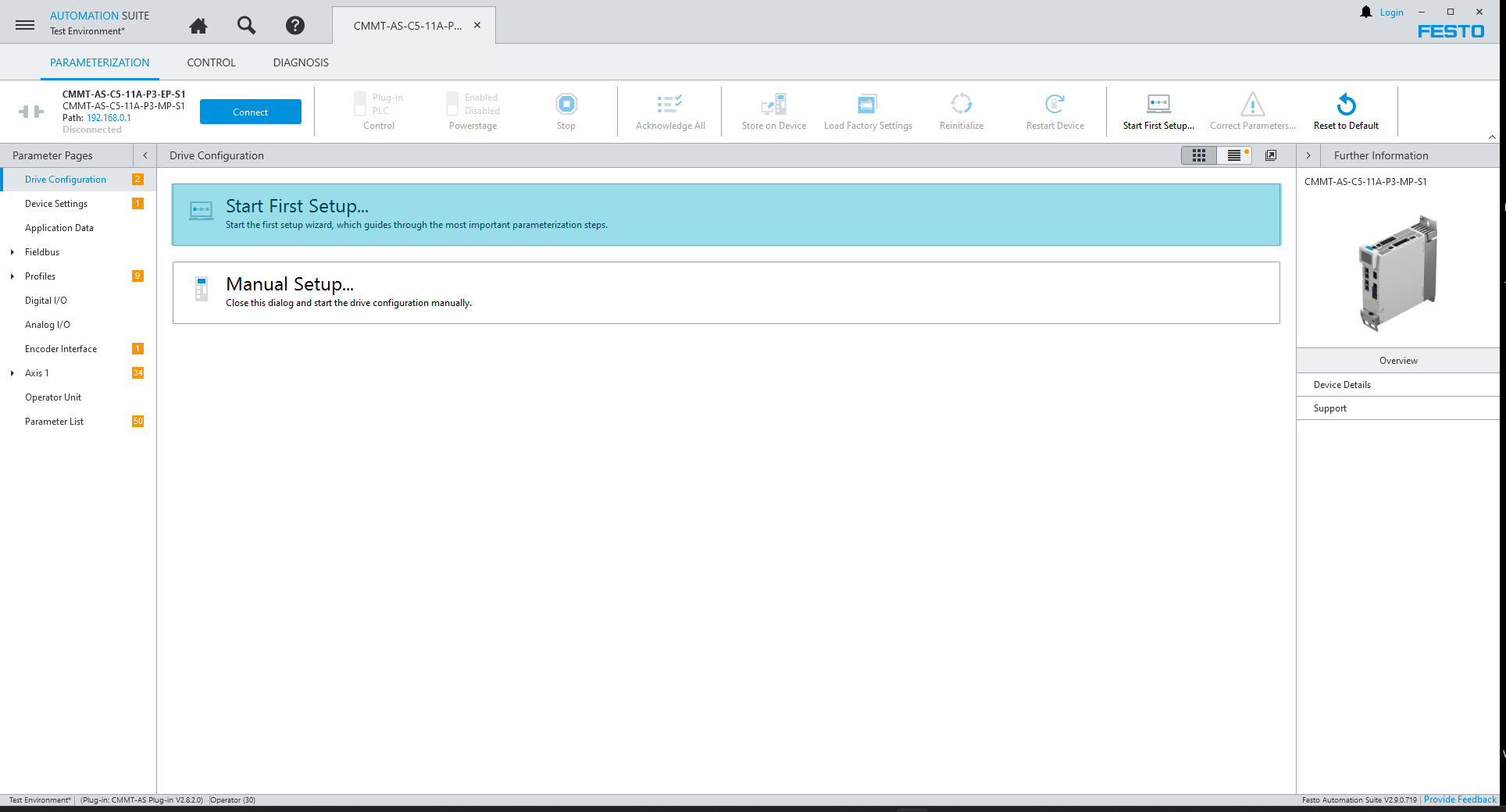
- Select Start First Setup to begin the configuration.
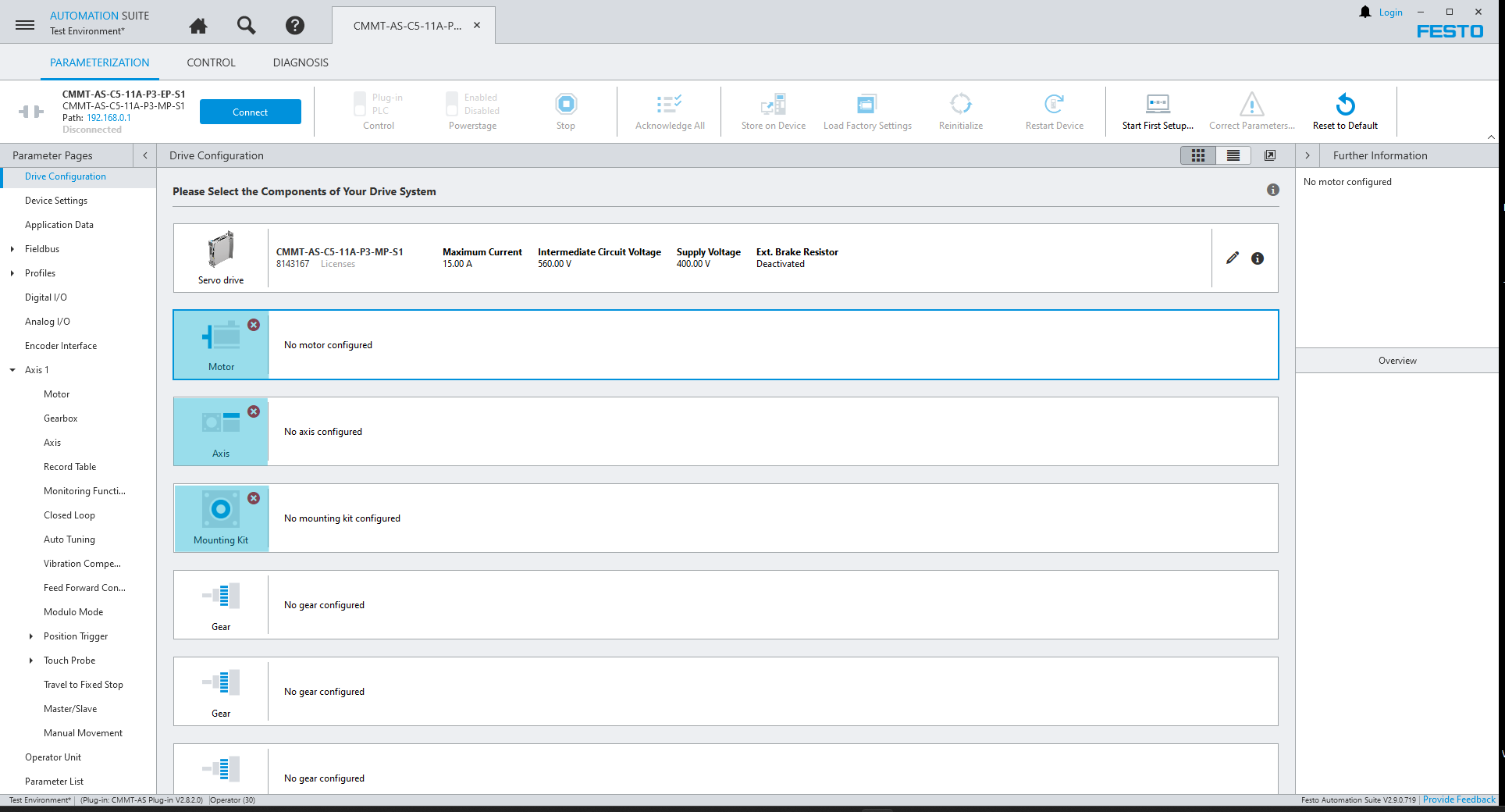
- Select the icons highlighted below to configure these components in the followings steps.
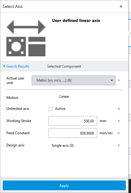
- Configure the Axis
To configure the axis, the Working Stroke is the length of the axis being controlled. Then one of the most important parameters to figure is the Feed Constant. The specifications that need to be known include the resolution of the encoder (50nm) and the resolution of the encoder input. CMMT drives have a 24-bit encoder interface. The resolution of the encoder can be used to calculate the number of pulses per your unit of measurement, in this project the actuator is scaled to millimeters (1 / 0.00005mm = 20,000 counts/mm). To then calculate the Feed Constant, divide 2^24 by the number of counts per mm (2^24 / 20,000 = 838.8608).
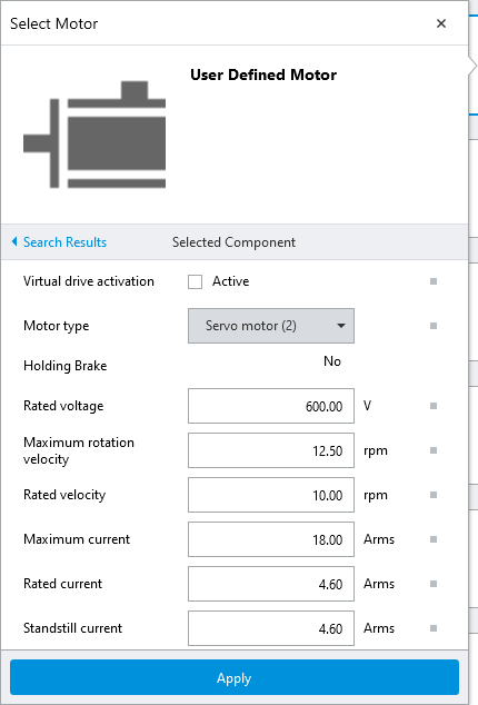
- Configure the Motor
- The Rated Voltage, Maximum Current, and Rated Current are all provided by the specifications of the motor.
- The Maximum Rotation Velocity and Rated Velocity are derived from the table in the motor specifications, but with the units that the feed constant will later be derived from, in mm/s instead of rpm
- The Standstill Current, unless otherwise specified, is either the same or slightly higher than the Rated Current.
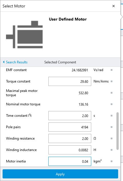
- The Torque Constant, in this case is the same as the force constant in the specifications.
- Although the specifications refer to an electrical time constant, the time constant for the motor refers to a mechanical time constant, which can be left at 2.00s for most applications.
- The Pole Pairs calculation is explained in Step 13 since you may need to enter a decimal, but this field only accepts integers.
- The Winding Resistance and Winding Inductance are all provided in the motor specifications.
- The Motor Inertia is calculated based on the mass and dimensions of the servo rotor.
- Set the encoder parameters based on the encoder being used for your application.
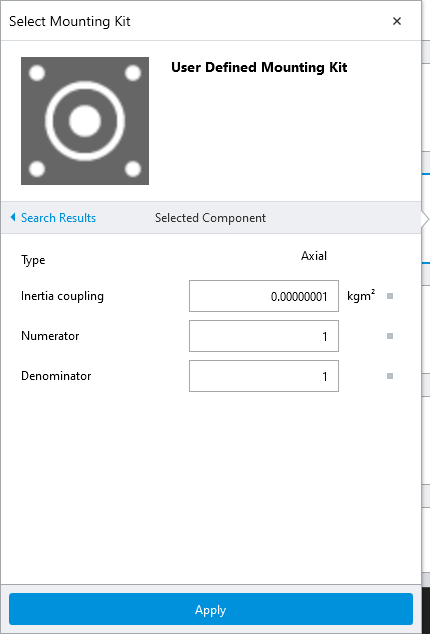
- Configure the Mounting Kit
- The Inertia Coupling should be set very low since there is physically no gearing for a linear motor.
- Set the gear ratio (Numerator : Denominator) to 1:1 since there is no external gearing.
- Change the following parameters per your project and then select Next.
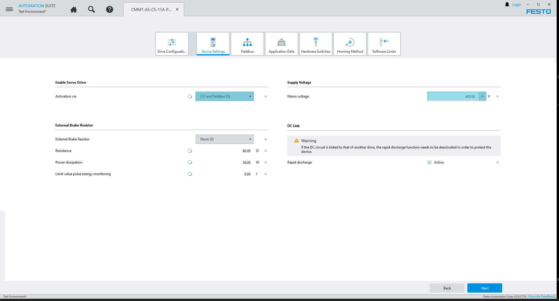
- Change the following parameters per your project and then select Next.

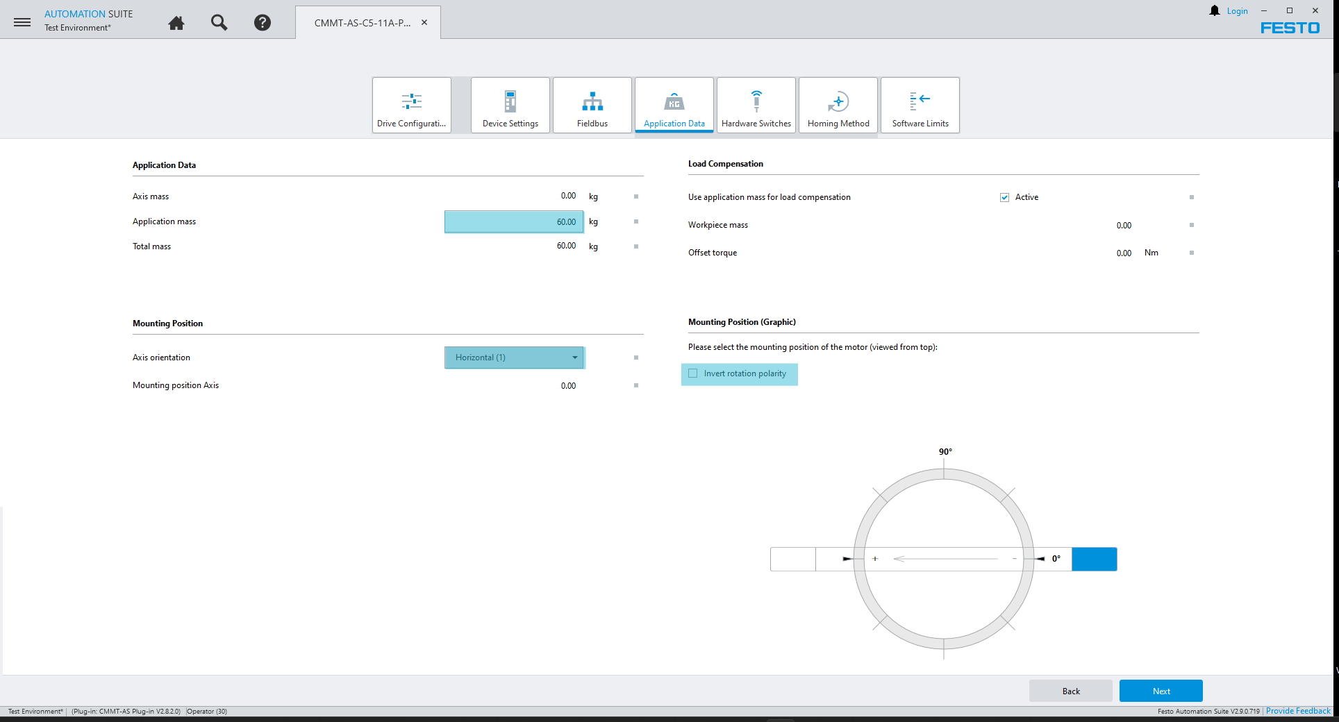
- Set the following parameters with the values from your project, it is recommended to start a setup with low risk of damage in the event of the axis moving unexpectedly. Then select Next to continue.
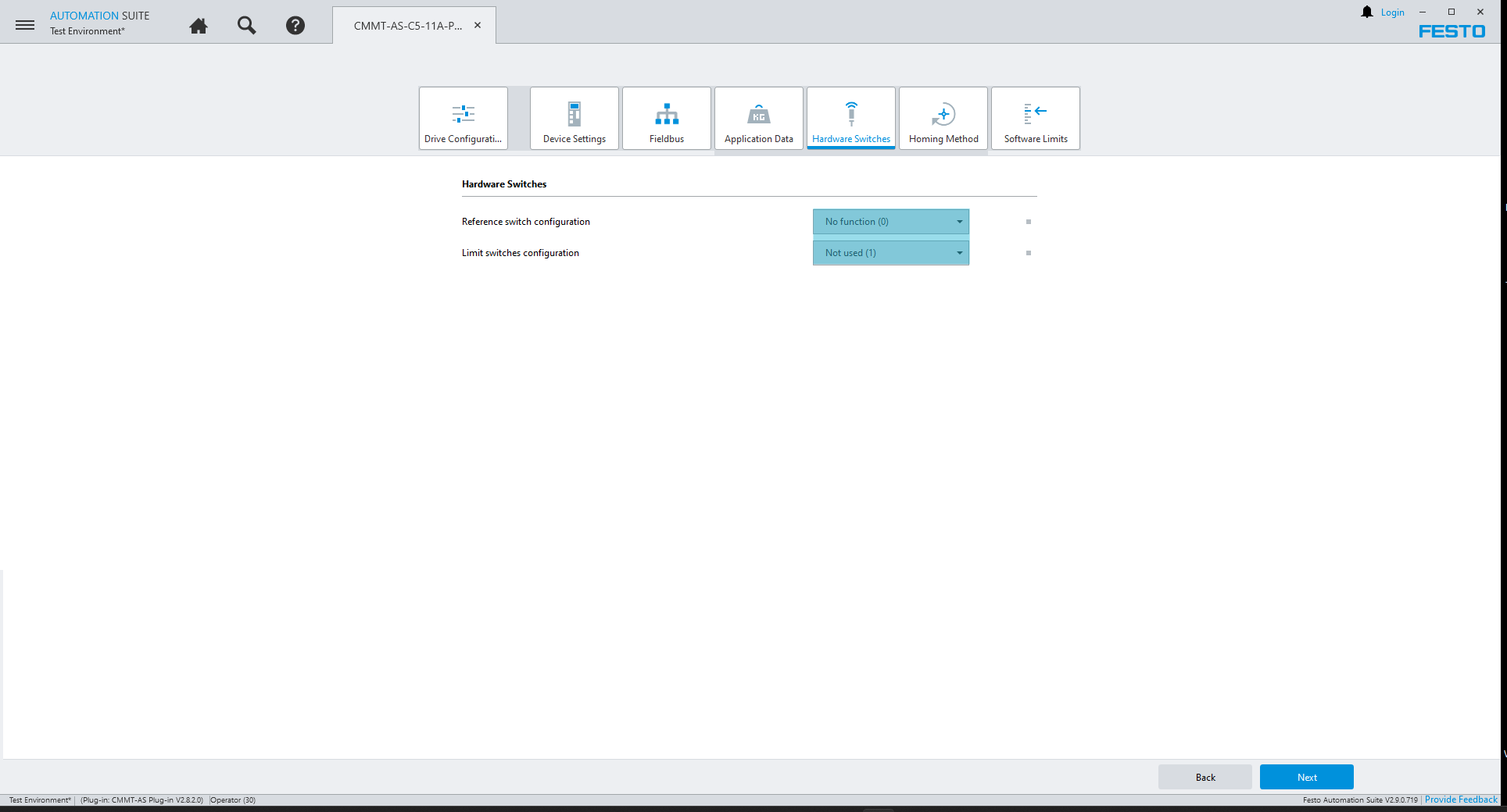
- Change the following parameters per your project and then select Next.
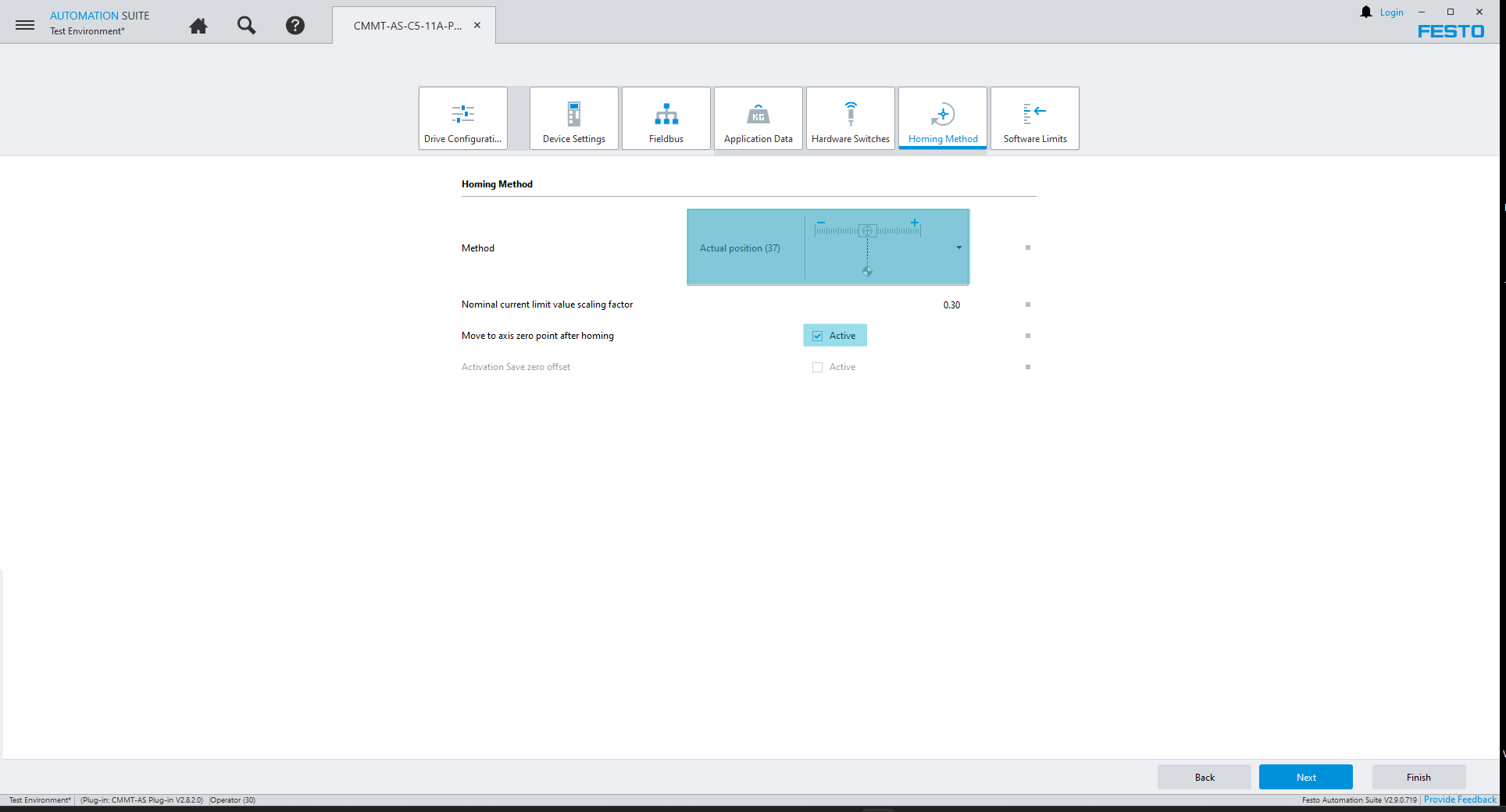
- It is recommended to begin with the following homing method and then this can be changed after verifying the axis is configured properly. Then select Next to continue.
- Remove the software limits temporarily as shown, it is recommended to set limits once the axis has been configured. The select Finish.

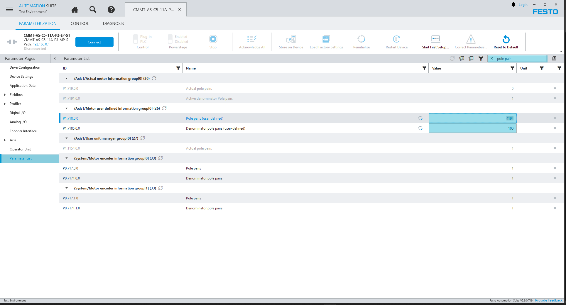
- Set the Pole Pairs
- Calculate the pole pairs by dividing the feed rate by the magnetic period (838.8608 / 20mm = 41.94304), in this instance using the value 41.94 is sufficient. Since this value is not an integer, a denominator is required to be set.
- Search ‘pole pair’ in the Parameter List on the left pane and enter a denominator so that the value for the pole pairs can be set in integers (4,194 / 100 = 41.94).
- Begin the initial start-up and tuning of the axis. It is recommended, especially with a 3rd party motor, to test with an unloaded system to reduce the risk of damage to the system.
Disclaimer
This post is provided solely for the purpose of offering setup assistance and general guidance. It is important to note that the ultimate responsibility for ensuring the overall safety and proper functionality of the machine lies with the System Integrator / End User. It is crucial to exercise caution, adhere to proper safety protocols, and consult relevant experts or professionals when necessary.
Although Festo employees will be contributing to this blog, please note this is not the official Festo support channel. For more timely technical support please reach out to your regional Festo support channel and/or consult user manuals and relevant documentation in www.festo.com