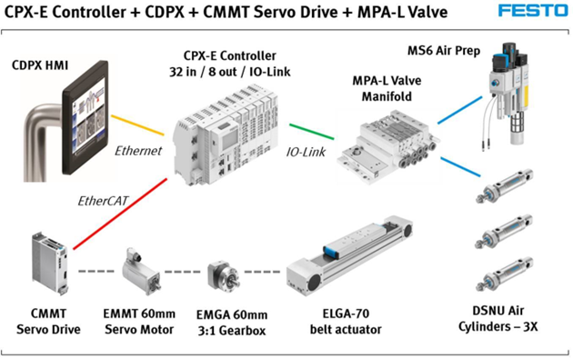
First Steps with PLC (CPX-E-CEC), Servo (CMMT) and HMI (CDPX)
By Bryan Moloney, Application Engineer, Festo USA

Hardware List
| Part no. | Type | Designation | Further Information |
| 5237644 | 60E-CB-MMLT51IO | Automation system | Operating Instructions |
| 8155214 | CDPX-X-B-W-7 | Operator unit | Application Note – CDPX; Designer Studio 2.0 |
| 1371245 | ELGA-TB-RF-70- | Toothed belt axis | Operating instructions |
| 5242197 | EMMT-AS-60-S-LS-RM | Servomotor | Operating instructions |
| 2297686 | EMGA-60-P-G3-EAS-60 | Gearbox | Operating instructions |
| 5340819 | CMMT-AS-C2-3A-EC-S1 | servo drive | Application Note – Commissioning of CMMT-AS in FAS with CPX-E-CEC |
| 558043 | MUE-70/80 | Profile mounting | Operating instructions |
| 1456616 | EAMM-A-N38-60H | Axial kit | Operating instructions |
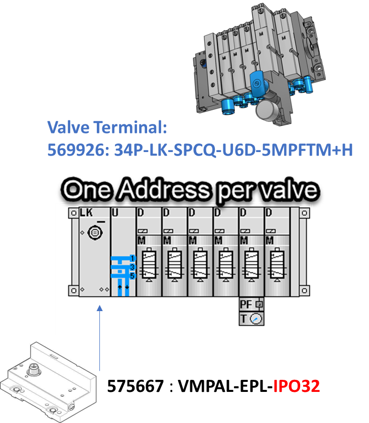
| 569926 | 34P-LK-SPCQ-U6D-5MPFTM+H | Valve manifold | Operating instructions |
Software List
| Name | Version | Link |
| Festo Field Device Tool -FFT | V2.10.5.198 | Maintenance of Ethernet based devices by Festo |
| Festo Automation Suite – FAS | 2.7.0.752 | Parameterisation, programming and maintenance of electronic devices by Festo |
| CMMT-AS Plug in for FAS | 2.7.0.578 | Plug-in for the configuration and parametrization of the servo drive CMMT-AS |
| CPX-E Plugin for FAS | 2.5.0.46 | Festo Automation Suite – Plug in |
| CDPX Target Support Package | v3.5.7.159 | CDPX Package for CoDeSys V3 |
| CMMT-AS Package / Refer to Directory | 3.5.16.48 | CMMT-AS Package for CodeSys |
| Function Block – CodeSys – CMMT-AS | 3.5.16.48 | PtP function blocks for Codesys 3.5 |
| EtherCAT XML – CMMT-AS | V031.0.7.10 | Device Description Files |
| Designer Studio | V4.5.0.224 | Festo Designer Studio for CDPX-HMI |
| Programming Software – CodeSys | CODESYS Provided by Festo | |
| Target Support Package CodeSys | Controller CPX-E-CEC-C1 (5226780) |
Note: Verify and match CODESYS software, firmware and Target Support Package for producing serial machines.
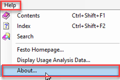
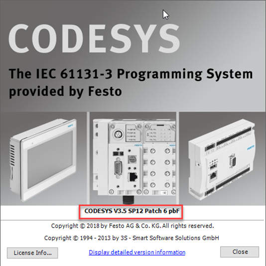
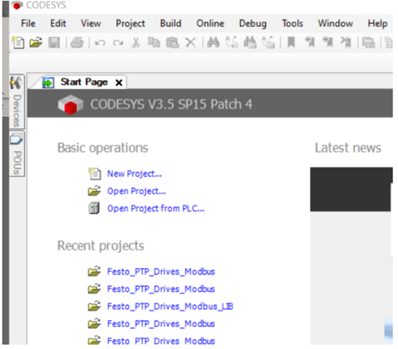
If the user already has CODESYS installed, the current version can be checked in the About… section:
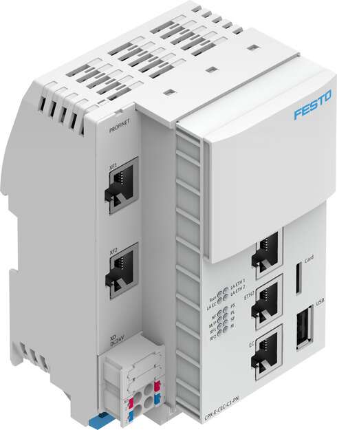
PLC (CPX-E-CEC)
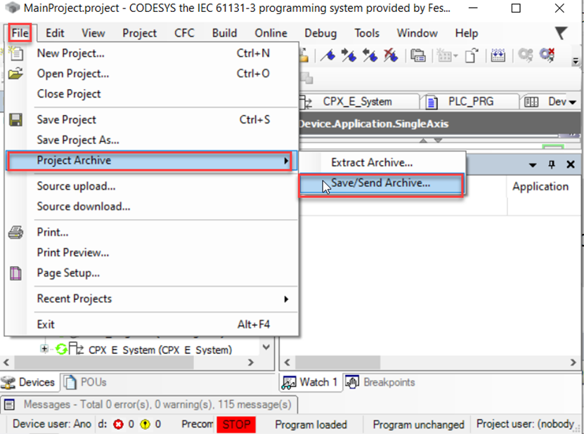
Create Project Archive and Control System Backup – If Applicable
Project Backup Method 1: Project Archive in CODESYS

Project Backup Method 2: Backup in Festo Field Device Tool (FFT)

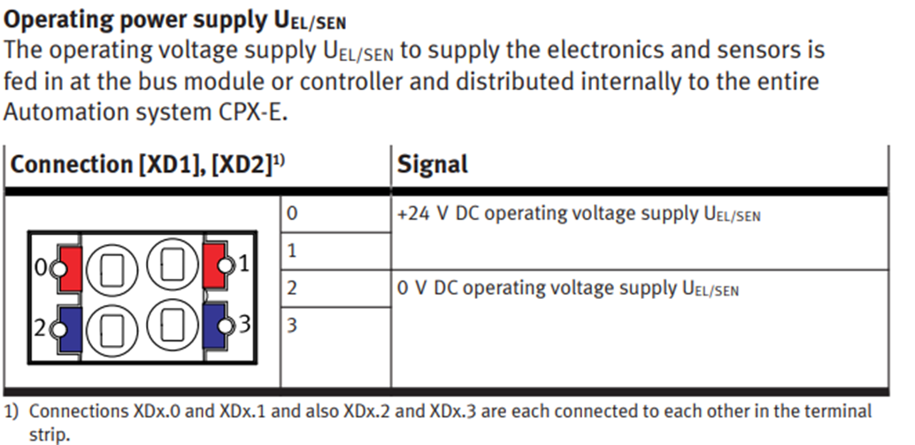
Power Supply Connections
Please refer to the operating instructions, which is provided by a link in the hardware description.
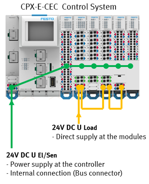
Load voltage supply UOUT The load voltage supply UOUT to supply the outputs is fed directly to the module separately for every module with outputs. In the following example with the output module CPX-E-8DO this is the output module CPX-E-4AO-UI and the IO-Link master module CPX-E-4IOL.
Ethernet Connections
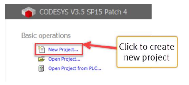
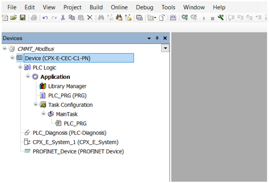
CODESYS Project
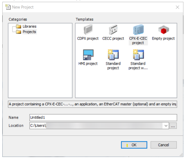
- Open software and create new project, use CPX-E-CEC project from template.
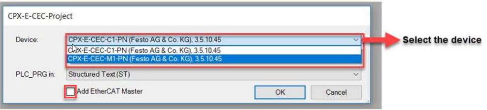
- Select the device along with the CODESYS version and programming language. For this exercise we will add an EtherCAT Master.
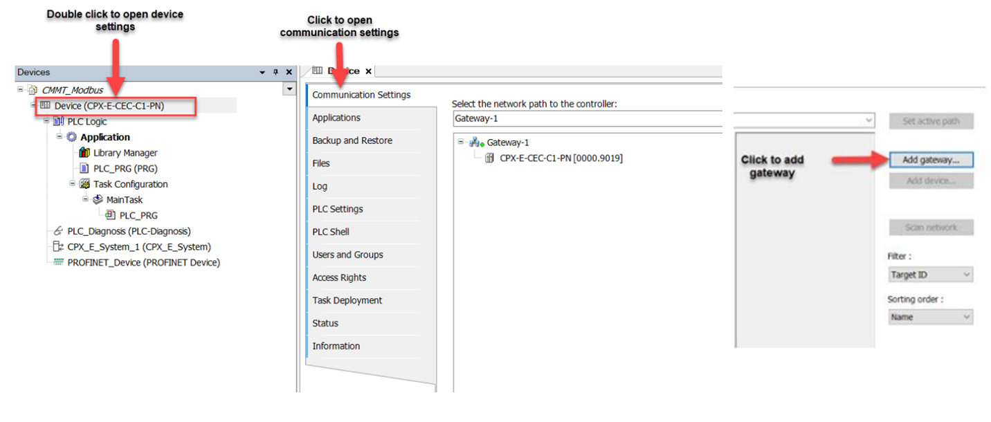
- Add Gateway to the project.
- Double click on the Device to open the device settings.
- Select communication settings to open Network settings.
- Add Gateway
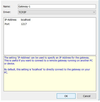
- Scan Network and Set Active Path.
- Select Gateway to scan the network to see if any controller is connected.
- If any controller is found it will be detected as shown below image.

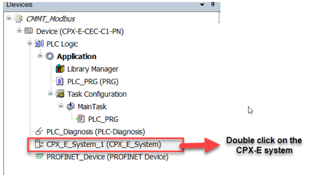
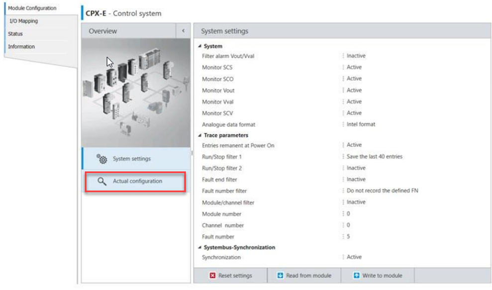
- Configure CPX-E Control System.
- Double Click on CPX-E-System in the CODESYS environment.
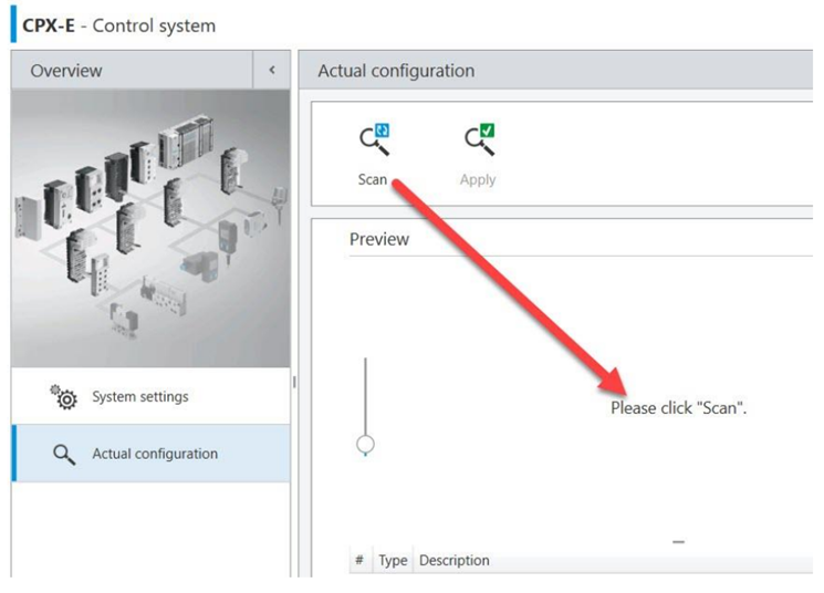
- Click on Actual Configuration to read the electronic data of each module.
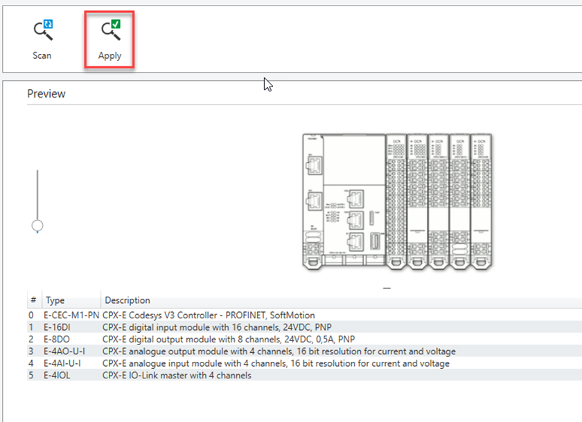
- Apply module configuration.
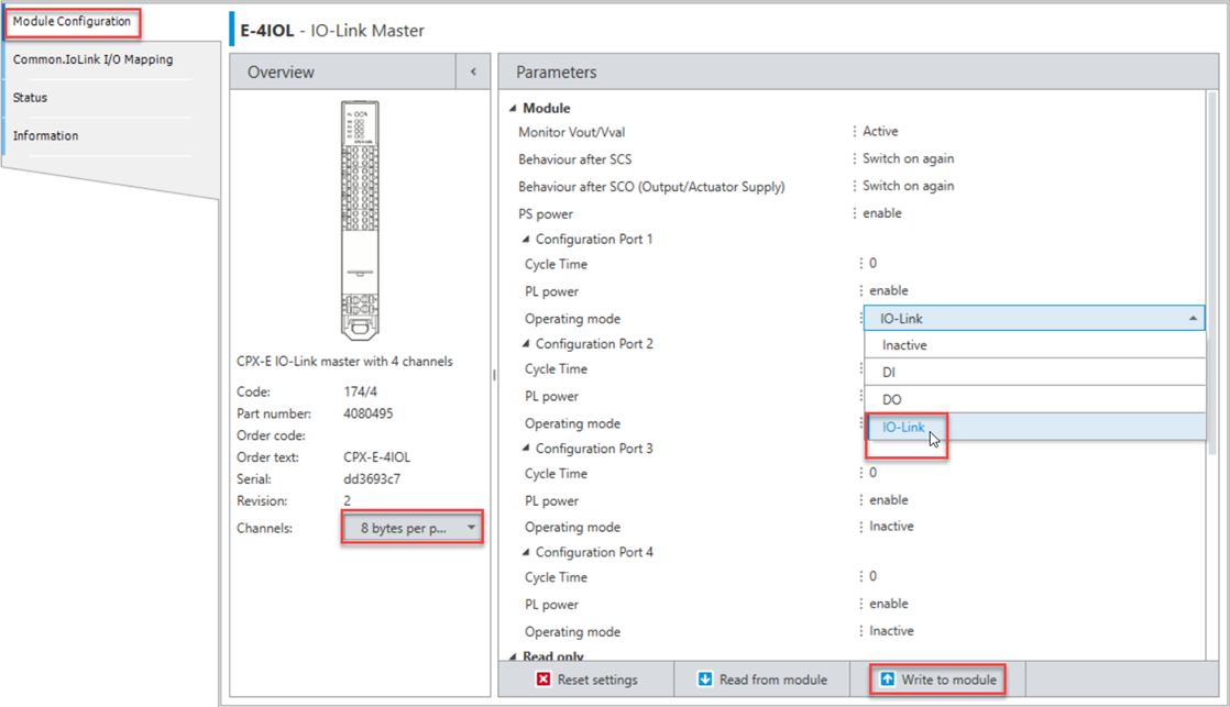
- IO-Link Master Module: Port Configuration
In this exercise we will be using an IO-Link device, therefore we will configure the IO-Link module.
- Enable port in module configuration settings and verify the channel is set to 8 bytes per port.
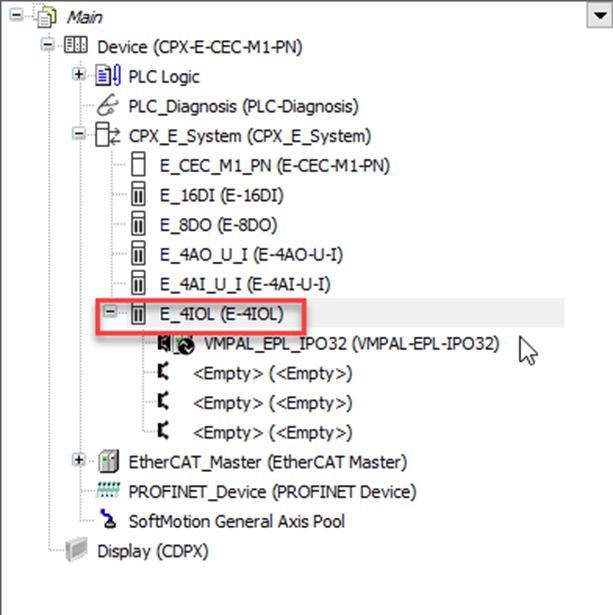
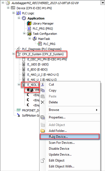
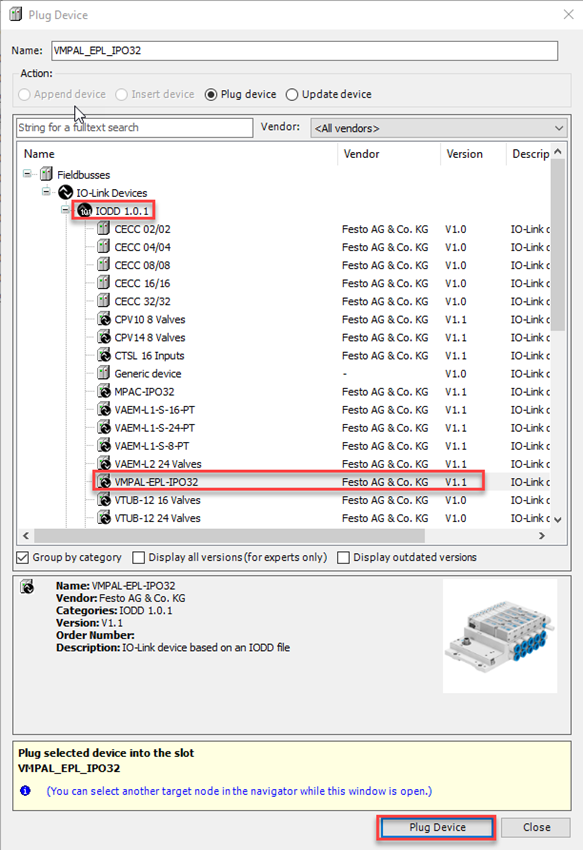
- Plug port for VMPAL-EPL-IPO32
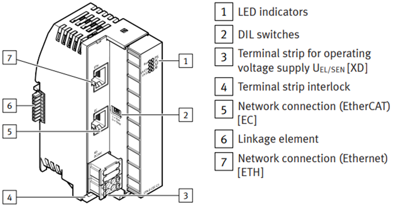
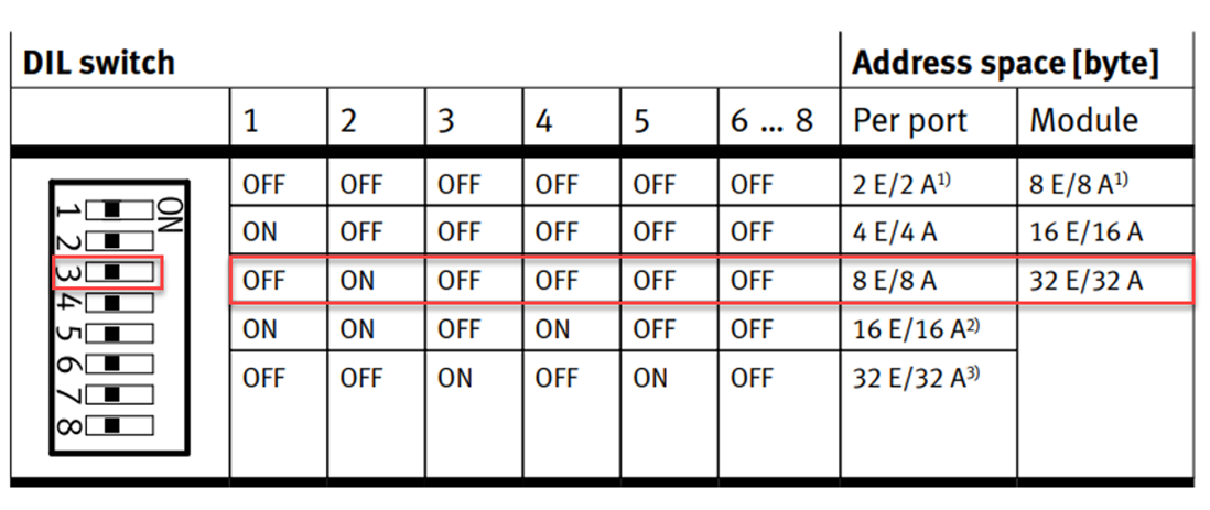
- Switch setting. The address space (inputs/outputs) provided by the module is set using DIL switches in Tab. 5 DIL switch.
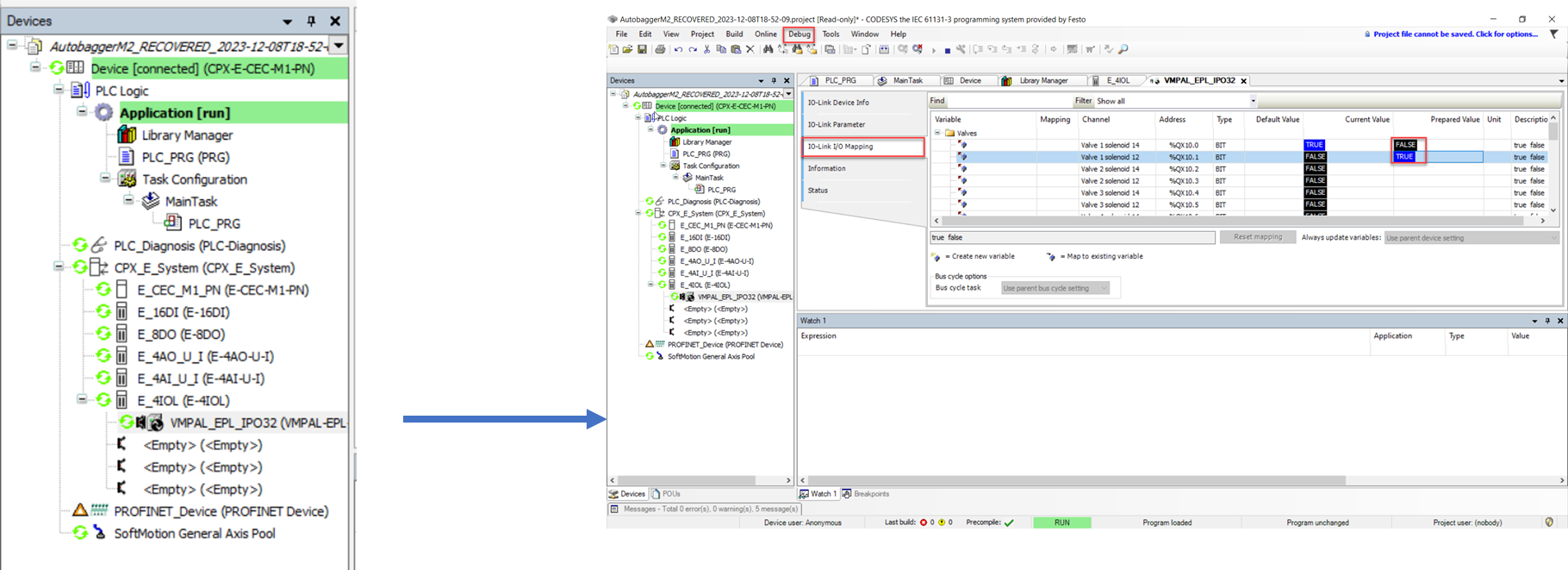
- Build and go online to test the data communication. Write values while in run mode using shortcut Ctrl-F7.
Servo drive (CMMT)

-
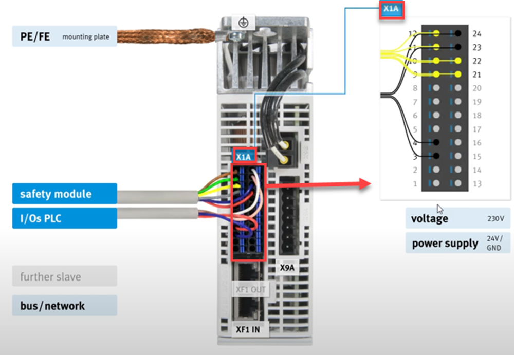
Electrical Installation
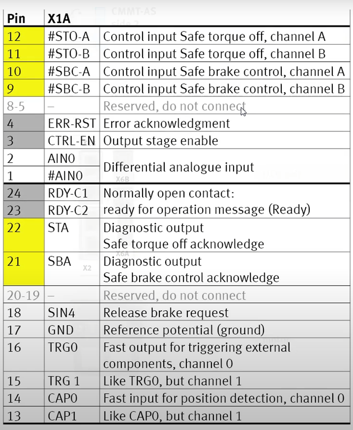
- Connections X1A
- Apply controlled or operating voltage – 24VDC to Pins 9-12 – Required for Operation
- Install PE/FE connection for Earth Grounding
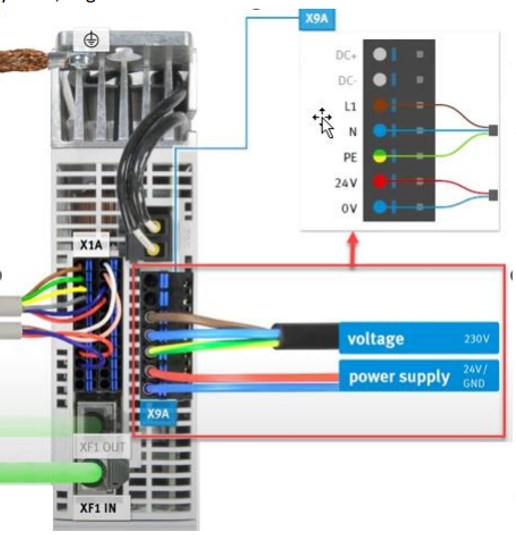
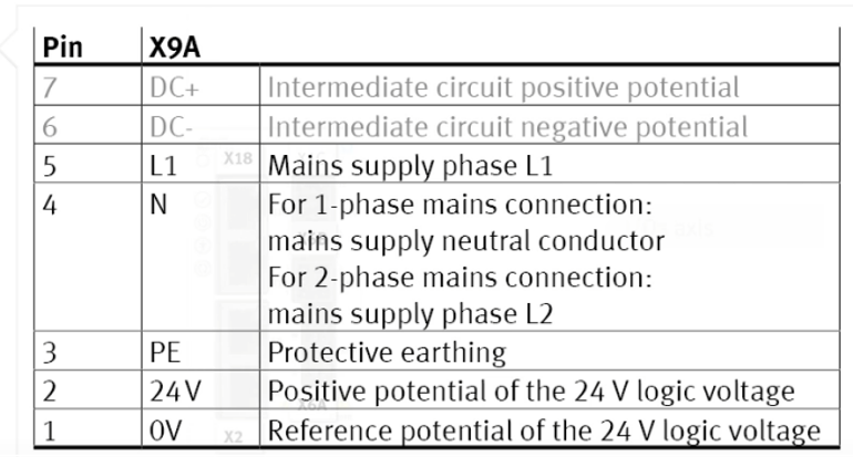
- Connections X9A
- Apply load and logic power – Pins 1-5
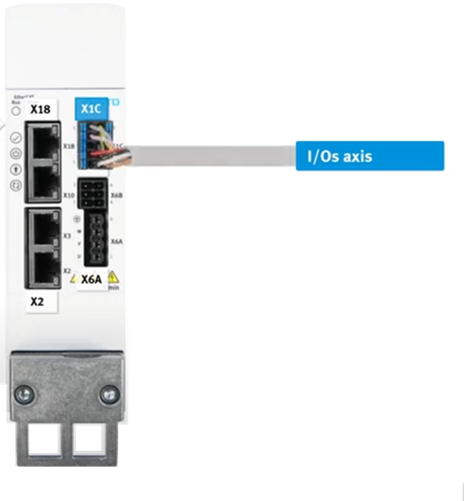
- Connections X1C
- Connection for Sensors, Switches and External Clamping Unit.
- No Connections are required for commissioning.

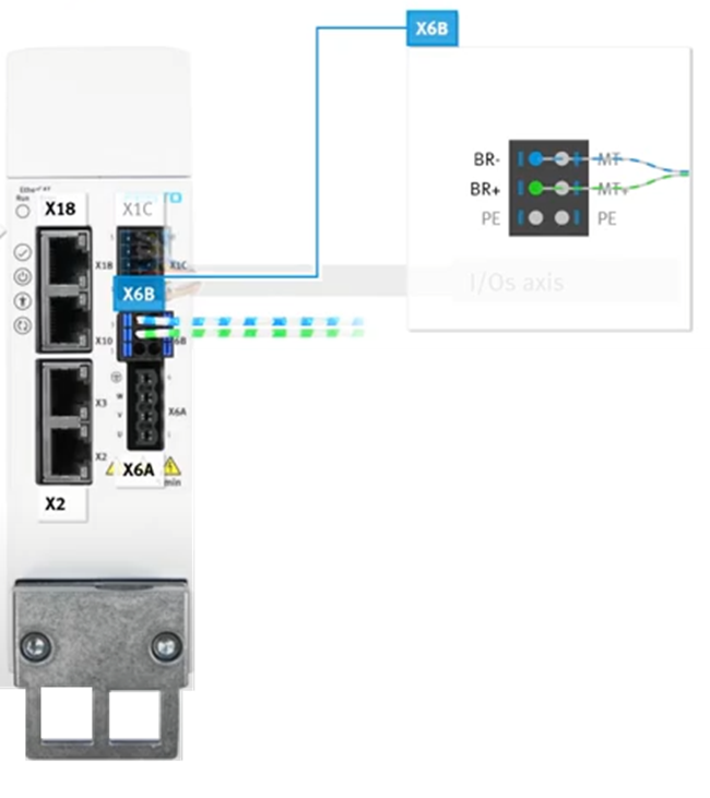
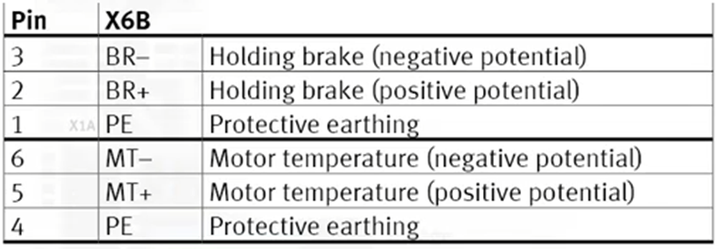
- Connections X6B
• Connection for External Motor Brake and temperature monitoring.
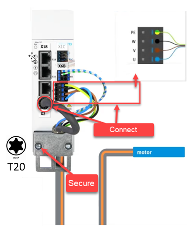
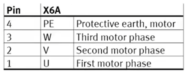
- Connections X6
- Connection for Motor Power and Encoder using X6, X6b and X2 ports (RJ45).
NEBU Cable Pinout 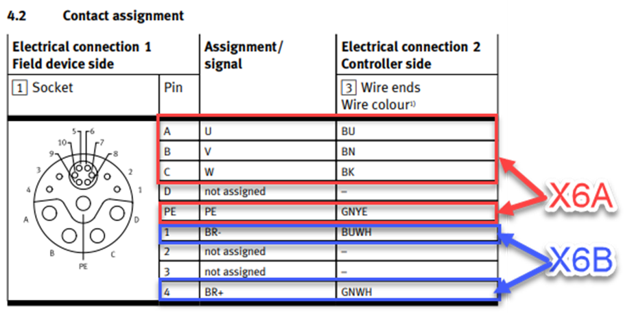
- Connections X18 and X19
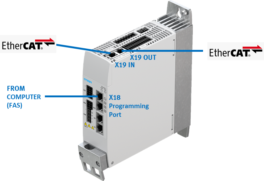
-
Software Commissioning
Refer to Application Note. This application nodes describes step by step how you configure a CMMT-AS-EC with CPX-E-CEC-M1-PN in Automation Suite and how you can use the Point-to-Point (PTP) libraries.
HMI (CDPX)
- Download or Transfer Projects
- Connect the HMI device to the computer with an Ethernet cable.
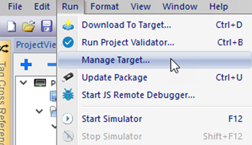
- In Designer Studio select the menu command, manage target.
You may have to ensure that the proper firewall policy has been configured in the computer to allow Designer Studio to access the network.
- Upload Project from existing HMI application or load existing project.
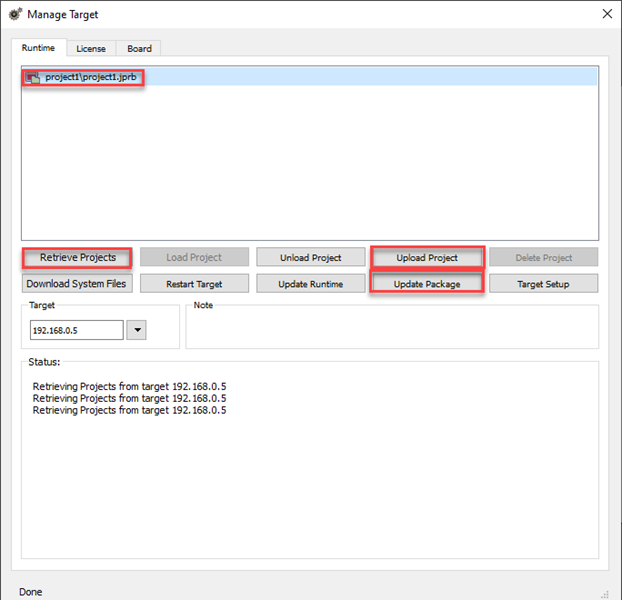
- Alternately, create an Update Package and copy it to a USB Flash drive.
- Select Manage Target / License
- Select Panel
- Type in Activation Key
- Click on Activate Panel
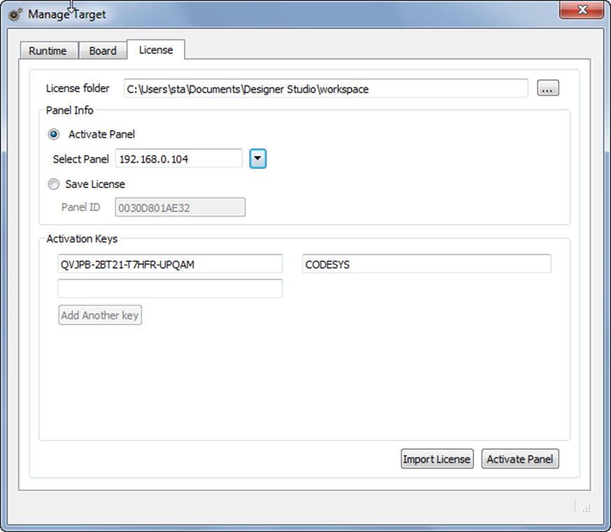
- Activation completed.
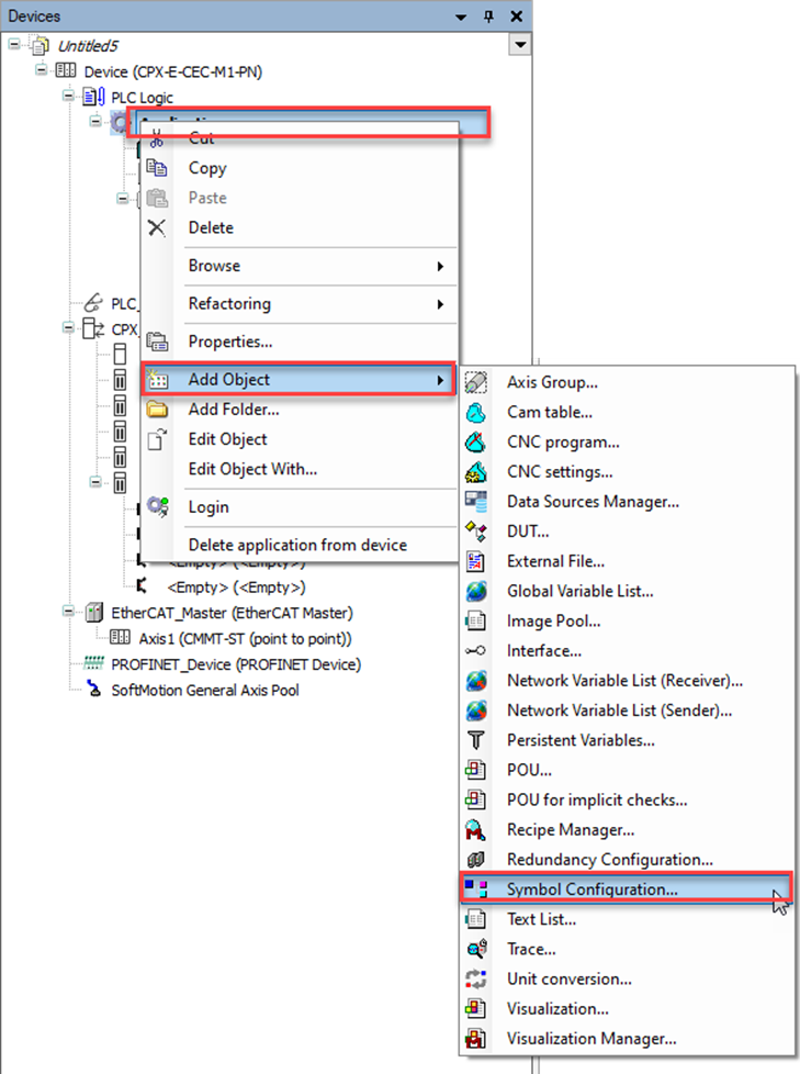
- In CODESYS, add Symbol Configuration.
- Add Symbol Configuration
- Include Data and symbols
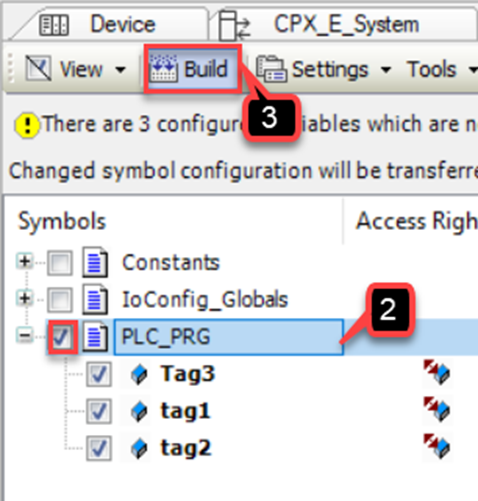
- Build the project
- Generate Code (online menu command
- Login and Out
- Look for .XML in Project Directory
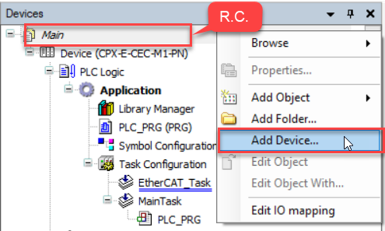
- Add CPX to CODESYS project by right-clicking on the project tree
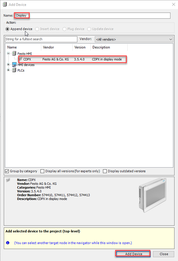
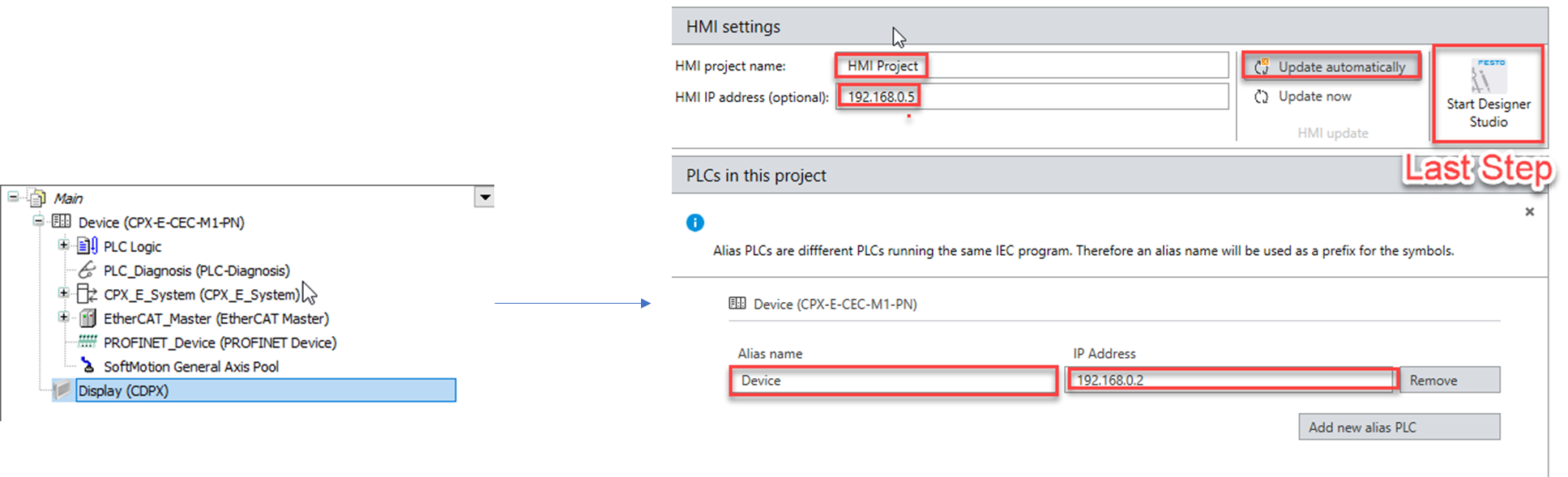
- Open the configuration settings of the display by double clicking the device.
- Create project name
- Device Name
- HMI IP Address
- Controller IP address
- Start Designer Studio
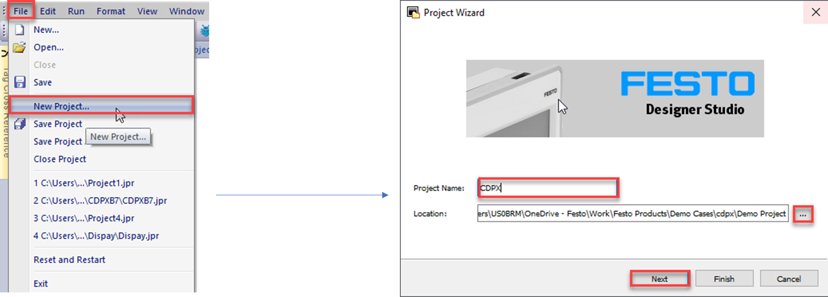
Back in Designer Studio:
- Create a New Project
- Create Project name
- Define Location
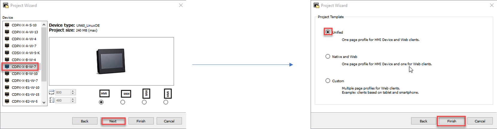
- Select Device
- Define Orientation
- Select Project Template
- Finish wizard
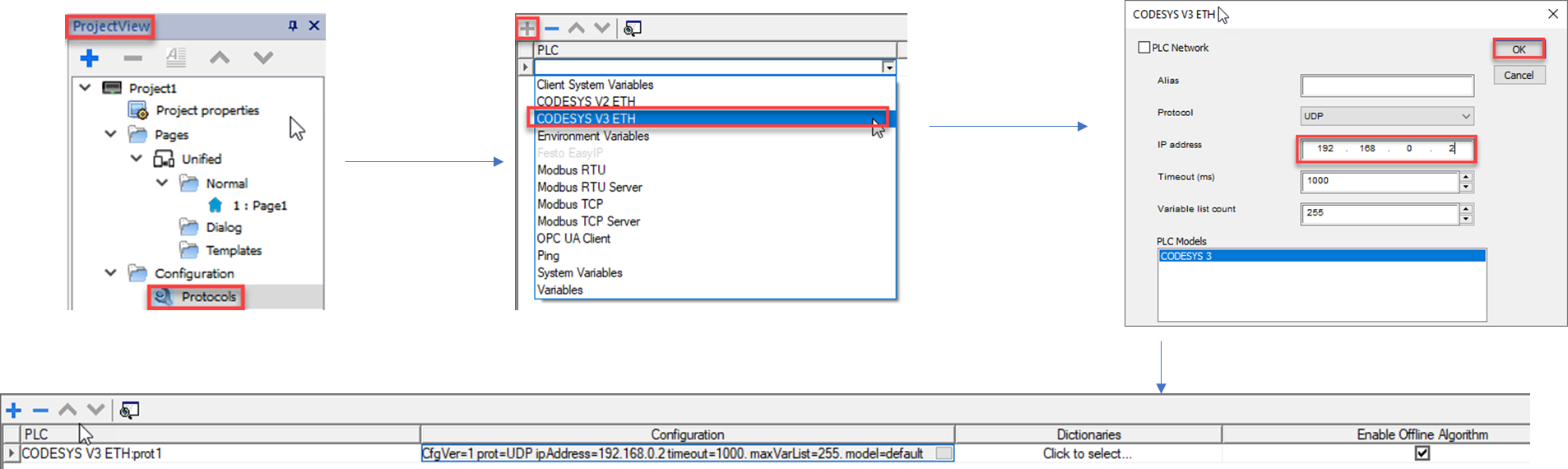
- Select Protocols in Project View
- Add Protocol CodeSys V3 ETH
- Select Tags in Project View
- Import data using .XML file from the CODESYS project directory
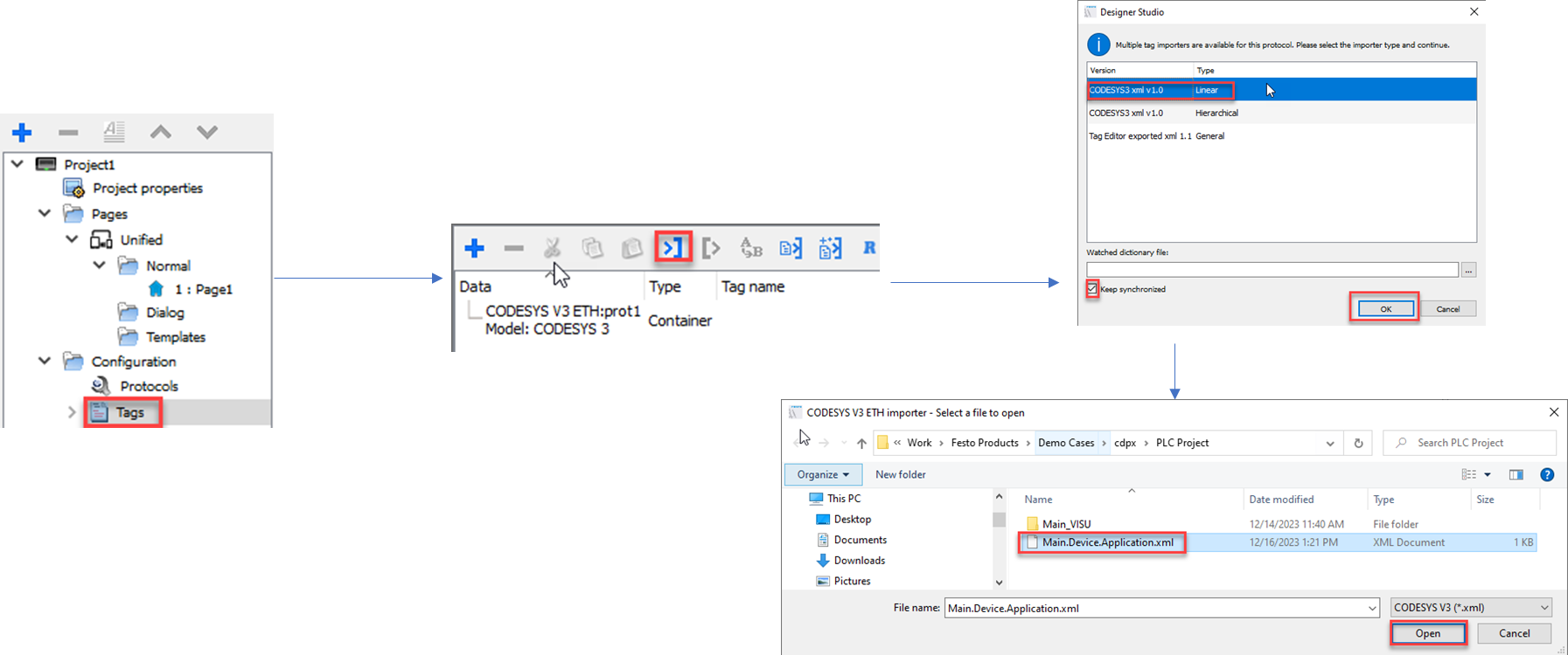
- Select Tags, symbols or data. Data should be grayed out.
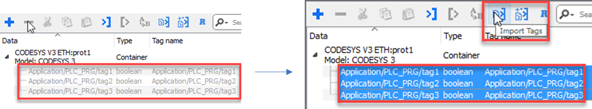
- Choose files to Import Tags
- This data should now be available in the widget gallery
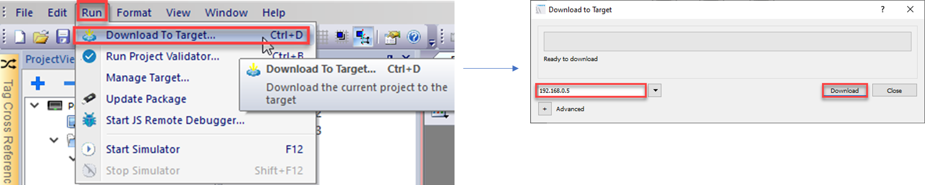
- Select the menu command Download To Target
- Verify IP address for HMI
- Download
- Save All
Disclaimer: This post is provided solely for the purpose of offering setup assistance and general guidance. It is important to note that the ultimate responsibility for ensuring the overall safety and proper functionality of the machine lies with the System Integrator / End User. It is crucial to exercise caution, adhere to proper safety protocols, and consult relevant experts or professionals when necessary.
Although Festo employees will be contributing to this blog, please note this is not the official Festo support channel. For more timely technical support please reach out to your regional Festo support channel and/or consult user manuals and relevant documentation in www.festo.com