Slow-Speed Tuning Example (Electromechanical Actuator)
Glen Burgess, Principal Controls Engineer, Re:Build DAPR Engineering
Shane Roy, Mechatronics Application Engineer, Festo USA
The purpose of this note is to describe an example application where an EGC actuator was tuned to move at 0.02mm/s without deviating more than ±10%.
Introduction
A customer approached Festo for a solution involving an inductive heater that needed to traverse a part at a very slow and consistent speed of 7.8 cm/hour (approximately 0.02 mm/s). In most motion applications, cycle time is a key factor in evaluating system performance, so component specifications typically emphasize maximum speeds where motors are rated in rpm and linear axes in mm/s, for example.
However, in applications where very low speeds are required, special consideration must be given to system design. Especially when the velocity needs to be more precise than the absolute position. One common approach is to use a high-ratio gearbox, allowing the motor to operate at a more stable, higher speed while still achieving slow movement at the axis. Gearboxes are typically selected to keep the motor running at a minimum of 200–300 rpm, which has traditionally been a practical lower limit for servo motors. Although advancements in servo technology have reduced this minimum, 200–300rpm remains a reliable target in many applications.
In terms of mechanical design, a ball screw axis offers better control at low speeds due to its rigidity, in contrast to a toothbelt axis, which can introduce challenges from its natural elasticity. However, ball screws and high-ratio gearboxes add cost. A more cost-effective solution may be to use a lower-ratio gearbox with a well-tuned toothbelt axis—provided it can maintain the required precision and stability at low speeds.
Application Details
The following Festo components were used for the project:
- 1x CMMT-AS-C2-3A-MP-S1 (Single-Phase AC Servo Drive)
- 1x EMMT-AS-60-S-LS-RM (Brushless Servo Motor)
- 1x EMGA-60-P-G20-EAS-60 (20:1 Gearbox)
- 2x EGC-70-1900-TB-KF-0H-GK (1900 mm Stroke Toothbelt Linear Actuator, 2 axes driven by one motor and a connection shaft)
- 1x KSK-70-900 (900 mm Length Connection Shaft)
The main system requirements included:
- Mass of about 100 kg mounted on top of the axis
- Axis will travel horizontal
- Minimum speed of 7.8 cm/hr
- Maximum deviation in velocity of ±10%
For this application, the motor speed was calculated with the following information: feed constant for the EGC size 70 is 78 mm/rev, 20:1 gearbox, travel speed of 7.8 cm/hr.
Converting 7.8 cm/hr to mm/min: 7.8 cm/hr x 10 mm/cm x 1 hr / 60 min = 1.3 mm/min
Converting 1.3 mm/min to rpm at the gearbox: 1.3 mm / min x 1 rev / 78 mm = 0.0167 rpm at the gearbox
Converting 0.0167 rpm at the gearbox to rpm at the motor: 0.0167 rev/min x 20 rev (motor) / 1 rev (gearbox) = 0.333rpm
Therefore, the motor would run at about 1/3 rpm which is significantly lower than the typical lower limit of a servo motor. With a standard absolute encoder for the EMMT motors, there are 18 bit or 2^18 = 262,144 pulses per revolution. Therefore, rotating at 1/3 rpm there are 87,381 pulses per minute and 1,456 pulses per second. With this many pulses it seemed feasible to be able to tune the system and not utilize a higher ratio gearbox.
Tuning
Electric Motion Sizing (EMS) generates a commissioning file with preconfigured tuning parameters to simplify setup of the complete handling system, including the drive, motor, and axis, provided the input parameters are reasonably accurate. In this application, the target speed was below EMS’s typical operating range. As a result, the tuning process began with parameters generated for a higher speed within EMS’s supported range (in this case, 7.5 mm/s).
Tuning strategies can vary depending on system mechanics and user preferences. The focus for this application was first on optimizing Velocity Control to ensure consistent motion, followed by fine-tuning Position Control to improve speed consistency during positioning moves.
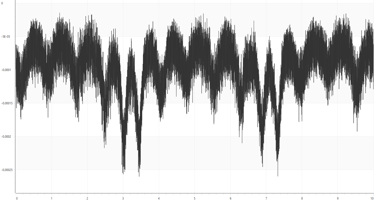
To evaluate tuning effectiveness, the Trace functionality of the CMMT drive was used. By monitoring actual vs. setpoint position and velocity over time, changes in system behavior could be observed and correlated with adjustments to the tuning parameters. The following trace shows the actual velocity over time in seconds, when the velocity was set to 0.10 mm/s. Even set at a higher velocity than the end goal, the velocity deviated by over 150%.
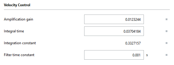
For the first tuning process, the axis was set with a velocity move at the desired 0.02 mm/s. Since this type of move utilizes the Velocity Control parameters, the options to help tune this type of move include an amplification gain, integral time, and filter time constant. The before and after tuning parameters are shown below:
Before
After
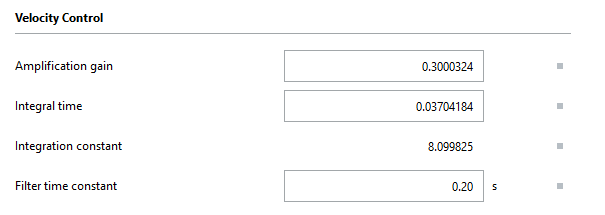
The filter time constant was increased to compensate for the reduced frequency of encoder pulses at low motor speeds. A time constant that is too low causes the drive to overreact to small velocity changes, resulting in oscillations where the actual velocity rapidly fluctuates above and below the setpoint. On the other hand, a time constant that is too high delays the drive’s response, allowing the actual velocity to drift significantly from the setpoint before corrective acceleration is applied.
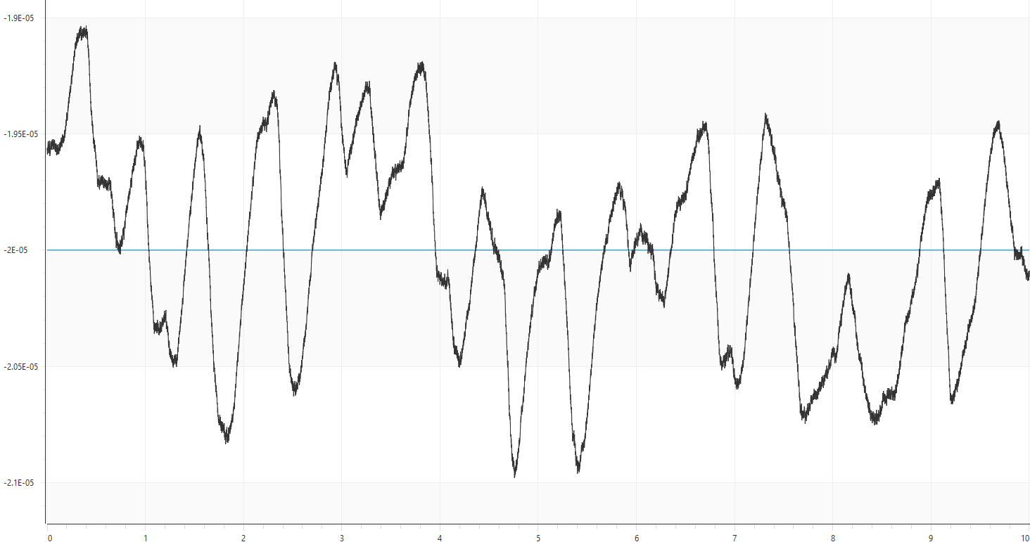
Once the filter time constant was adjusted, the velocity amplification gain was tuned by testing values slightly above and below the initial setting. Increasing the gain reduced the velocity deviation around the setpoint, up to a certain point. Beyond this optimal value, further increases in gain caused the deviation to worsen again. While the integral time could have been adjusted to refine the response further, it was deemed unnecessary since the velocity deviation remained within ±10% of the setpoint. Below is a graph of the actual velocity over time in seconds, demonstrating at a setpoint of 0.02 mm/s the velocity deviated by up to about 0.001 mm/s or 5%:
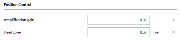
For the second tuning process, the axis was set to cycle between two absolute position moves, utilizing the Record Table functionality of the CMMT drives. The positions were arbitrary for this process, but the velocity was set to the same 0.02 mm/s as before. In this application, the Position Control parameters calculated by EMS performed very well. But slightly decreasing the position amplification gain decreased how aggressively the setpoint position changes over time to maintain a consistent velocity. Increasing or decreasing the amplification gain beyond this point started to increase the deviation of the actual velocity. The before and after tuning parameters are shown below:
Before
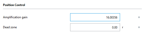
After
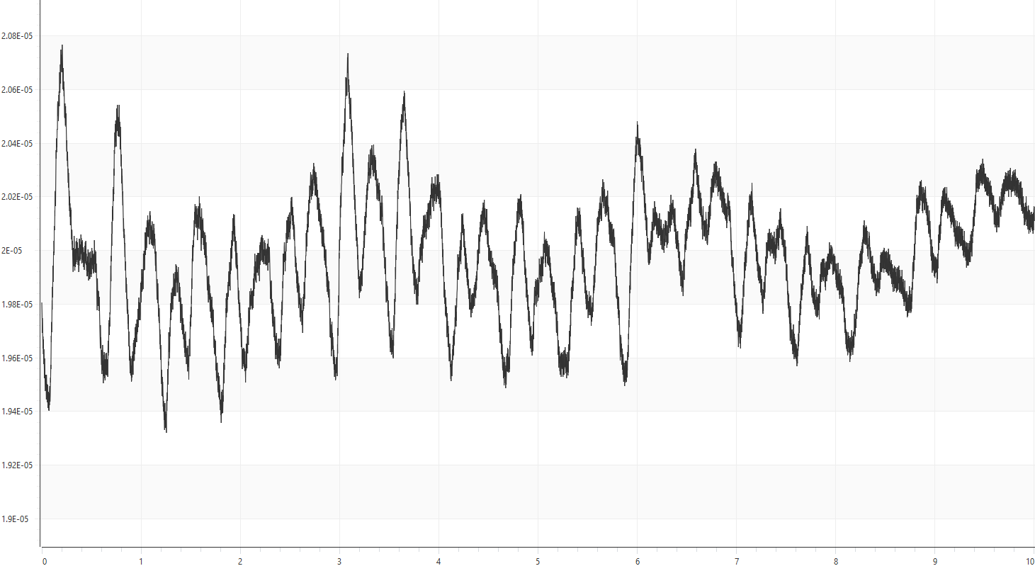
Below is a graph of the actual velocity over time in seconds demonstrating at a setpoint of 0.02 mm/s the velocity deviated by up to about 0.0008 mm/s or 4%:
The application also required the system to return to its starting position at a higher speed to restart the process. The new tuning parameters optimized for slow movement introduced excessive vibration at higher speeds due to increased velocity amplification gain. The CMMT drive supports multiple parameter sets that can be switched by the upper-level controller (PLC) to address this issue. This made it possible to store one set of parameters optimized for slow-speed operation and another for fast-speed return, with seamless switching between them via a single PLC command.
Disclaimer
This post is provided solely for the purpose of offering setup assistance and general guidance. It is important to note that the ultimate responsibility for ensuring the overall safety and proper functionality of the machine lies with the System Integrator / End User. It is crucial to exercise caution, adhere to proper safety protocols, and consult relevant experts or professionals when necessary.
Although Festo employees will be contributing to this blog, please note this is not the official Festo support channel. For more timely technical support please reach out to your regional Festo support channel and/or consult user manuals and relevant documentation in www.festo.com