Application Notes Siemens TIA Portal / Festo CPX-MPA Commissioning
The purpose of this post is to provide a workflow and instructions needed to commission CPX-MPA with Profinet and Siemens S7-1200 PLC. This document applies to TIA Portal V13 SP1. These instructions include two methods of configuration: manual and auto-scan technique.

Preparation: Hardware Description
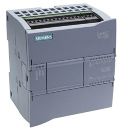
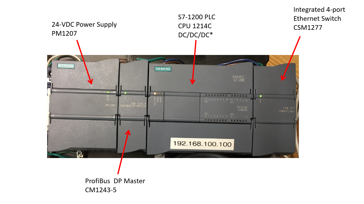
The PLC used in this example application has the following:
Note: The S7-1200 PLC has integrated I/O which can be accessed by hinge panels at the top and bottom of unit.
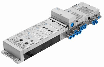
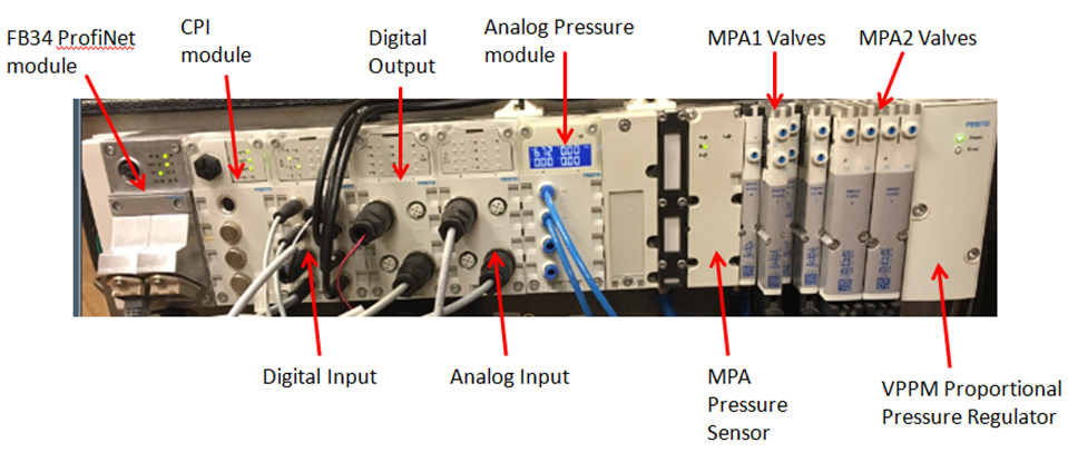
The Valve Terminal used in this example application has the following:
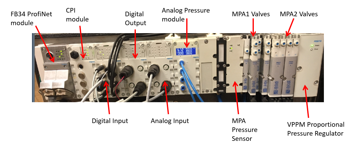
Preparation: Additional Hardware With Festo CPX-MPA, Siemens Controller
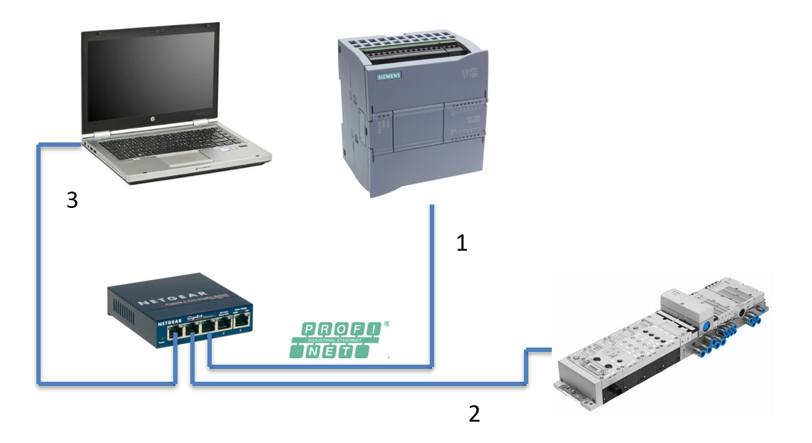
| Connection | Description | IP Address |
|---|---|---|
| 1 | PLC | 192.168.100.100 |
| 2 | Valve Terminal | 192.168.100.34 |
| 3 | PC | 192.168.100.50 |
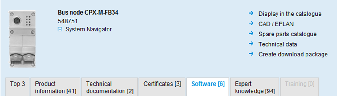
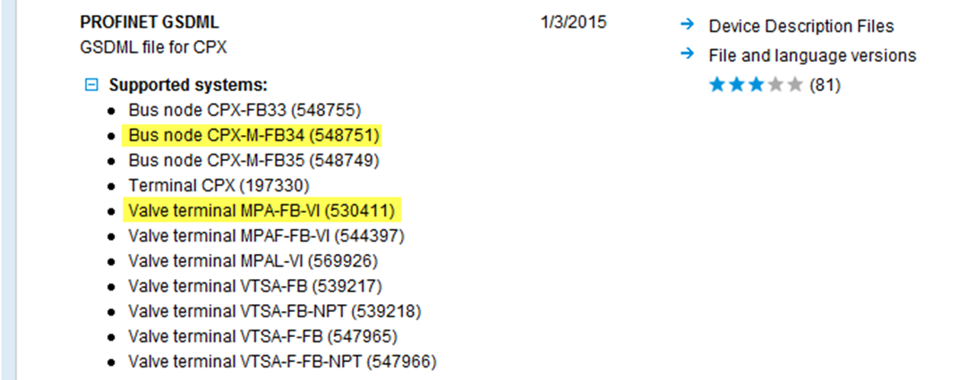
Preparation: Import Device Master File (GSDML)
- Locate GSDML in Festo Support Portal. Part #548751 was used in search window (CPX-M-FB34).
- Current version for GSDML is V2.31 released on 1/3/2015.
Commissioning With Siemens TIA Portal: Starting Project
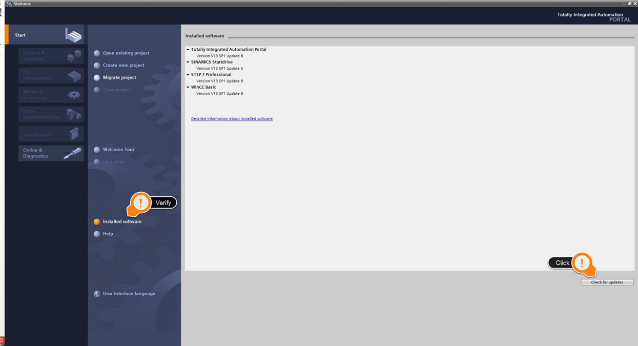
- Start TIA Portal V13: Current version V13 SP1, Update 8.
- Verify Revision. If SP1 isn’t installed, download and update at the following address.
- Check for any additional updates using the “Check for updates” link. Software updates do not appear until SP1 is installed.
Commissioning with Siemens TIA Portal: Create Project
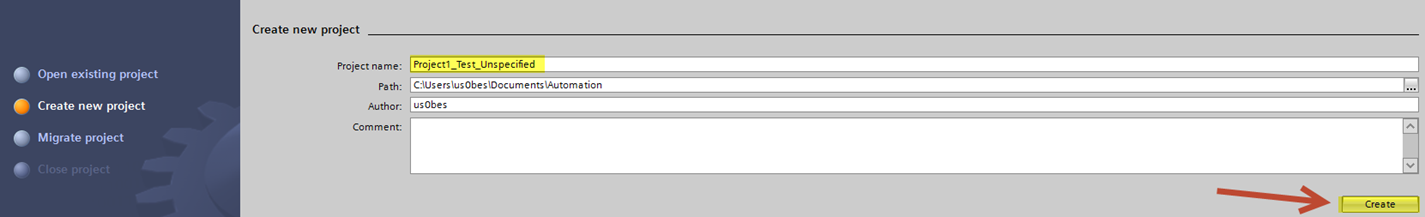
- Create New Project.
- Select Create after entering project name.
- Click “Open the project view”.
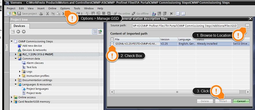
- Navigate to Menu Command for Options > Manage General Station Description Files (GSD).
- Navigate to the directory containing the GSDML file. Please extract contents first.
- Select the GSDML file using the check box.
- Install.
Configure the CPU (Scan Method)
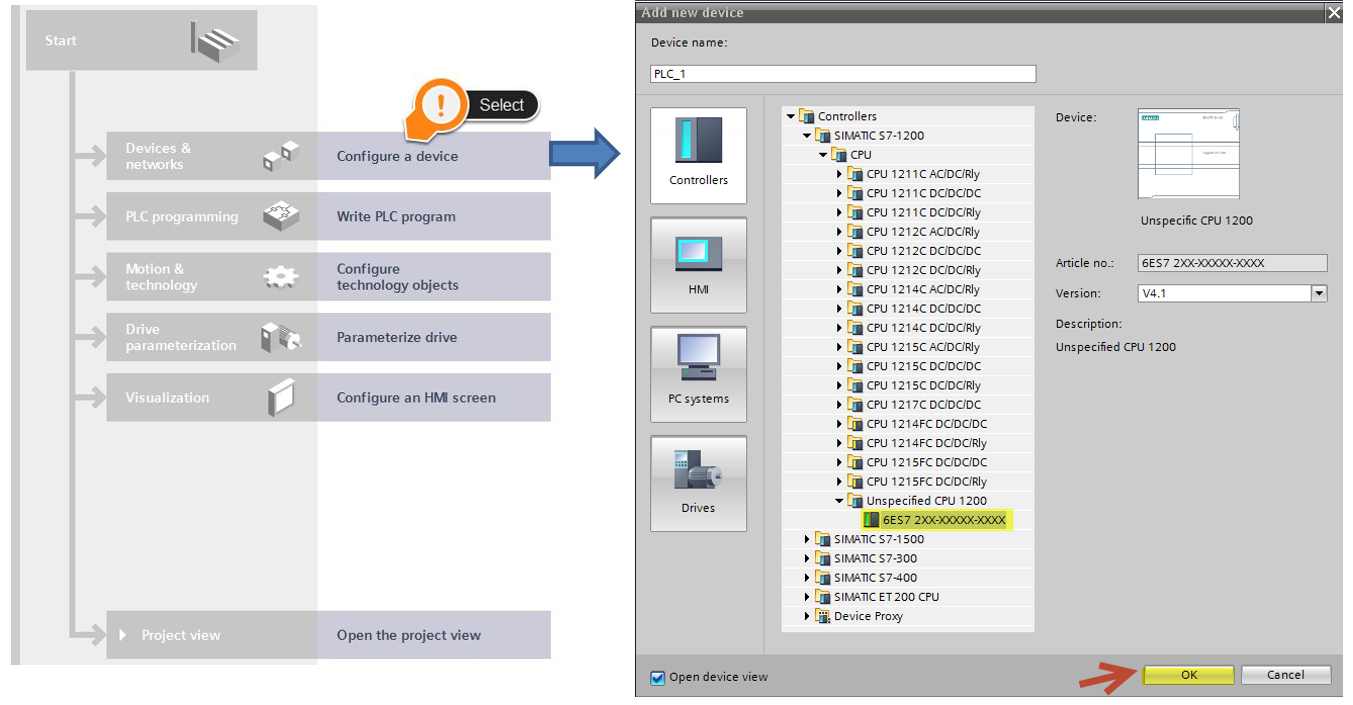
- Select “Configure a device”.
- Use the “Unspecified CPU 1200” listed in Simatic S7-1200 tree.
- Click “OK”.
Scan the network to detect CPU configuration:
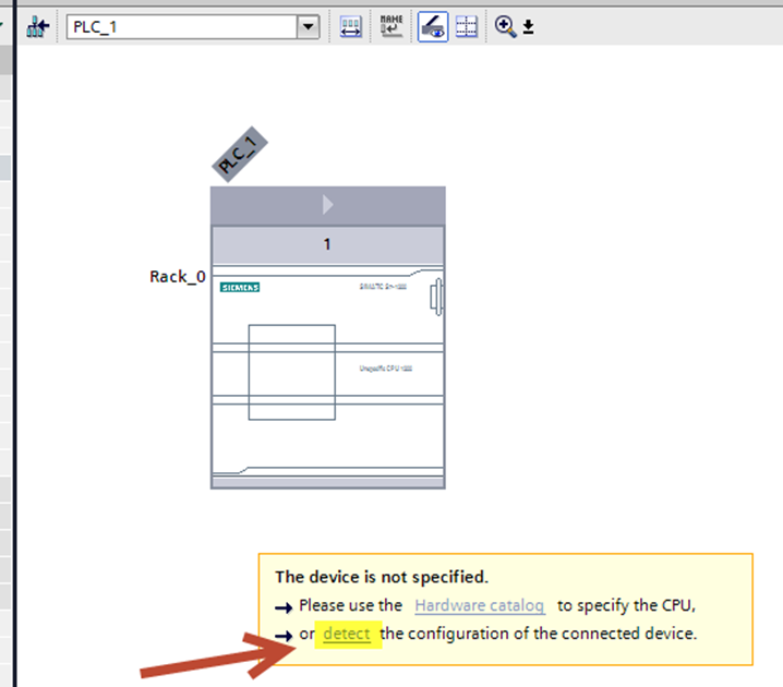
After selecting Unspecified CPU, you will see the window below that informs you the CPU is not specified. Click “detect” the configuration.
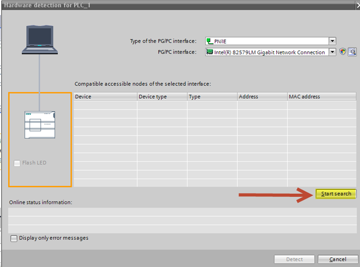
Click “Start search”.
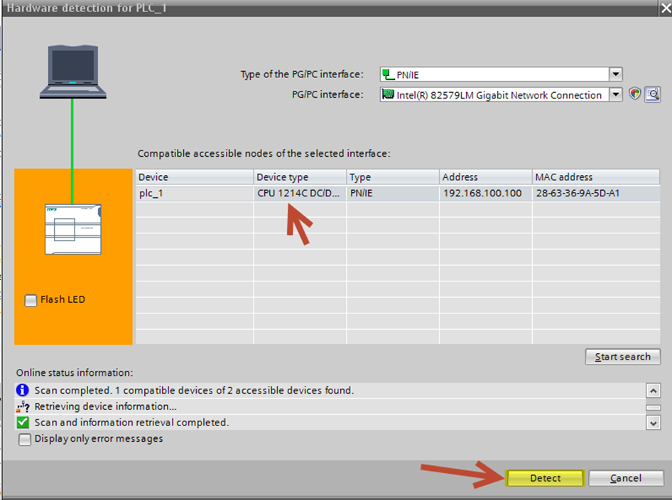
Detect CPU scan results
Notice the Device type CPU listed as 1214C DC/DC/DC & Address info.
Click “Detect” to accept these findings.
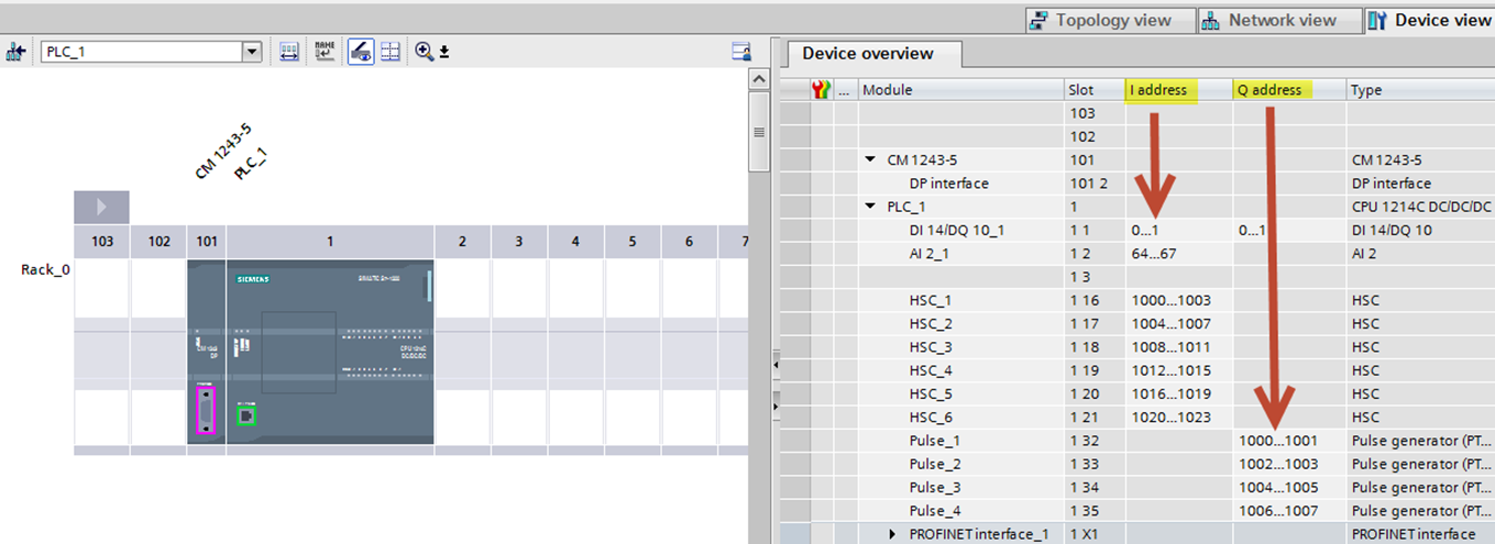
Notice CPU Device Overview
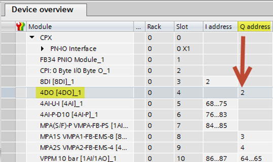
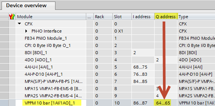
Once the CPU has been configured, review the module info and I/Q addresses listed in the Siemens Device Overview. The S7-1200 CPU has integrated Inputs and Outputs already configured.
Also notice that, although the CPU rack contains a Power Supply and Network Switch, there is no device shown in these positions. Leave the slots blank for this example, this will not affect the project.
Compile and Save Project
At this point, please compile and save the project. Double-click “Devices & networks” in the Siemens tree. Highlight the PLC and click Compile, then Save Project.
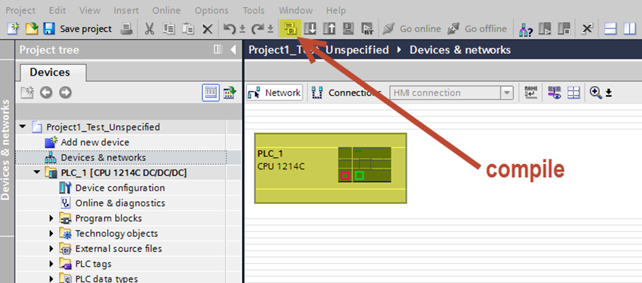
This ends the portion of configuring the CPU via scan method.
Configure the CPU (Manual Method)
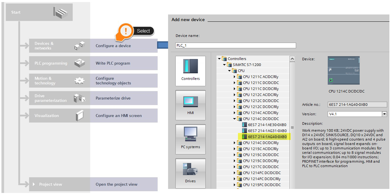
- Refer back to page 7 for creating a new project.
- After clicking on “Add new device”, find CPU 1214C DC/DC/DC listed in the Siemens tree. Use 6ES7-214-1AG40-0XB0.
- Click “Add” in lower RH corner.
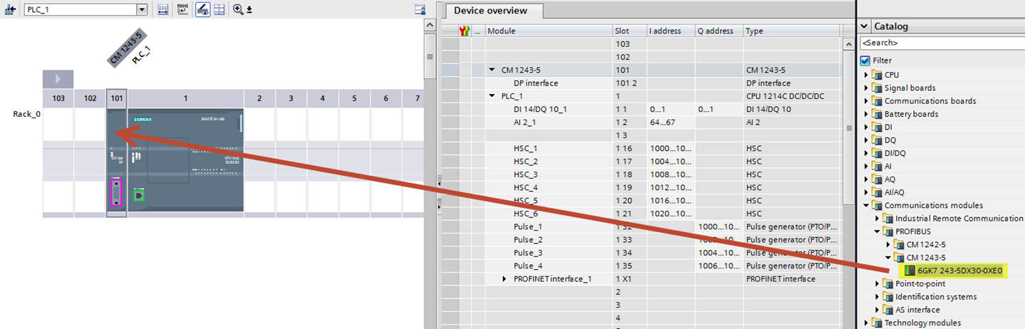
- Add the ProfiBus module to your configuration. Refer to the Siemens Hardware catalog. Find ProfiBus, then drag and drop the 6GK7 243-5DX30-0XE0 to slot 101 in the PLC rack.
- Double-click “Devices & networks” in LH Siemens tree.
- Highlight the PLC and click Compile.
- Save Project.
This ends the portion of configuring the CPU via Manual Method.
Configure the Festo Valve Terminal (Manual Method)
- Double-click “Devices & networks”.
- In the Hardware Catalog, find the CPX VT that fits your application. Our sample uses CPX. Drag and drop on workspace.
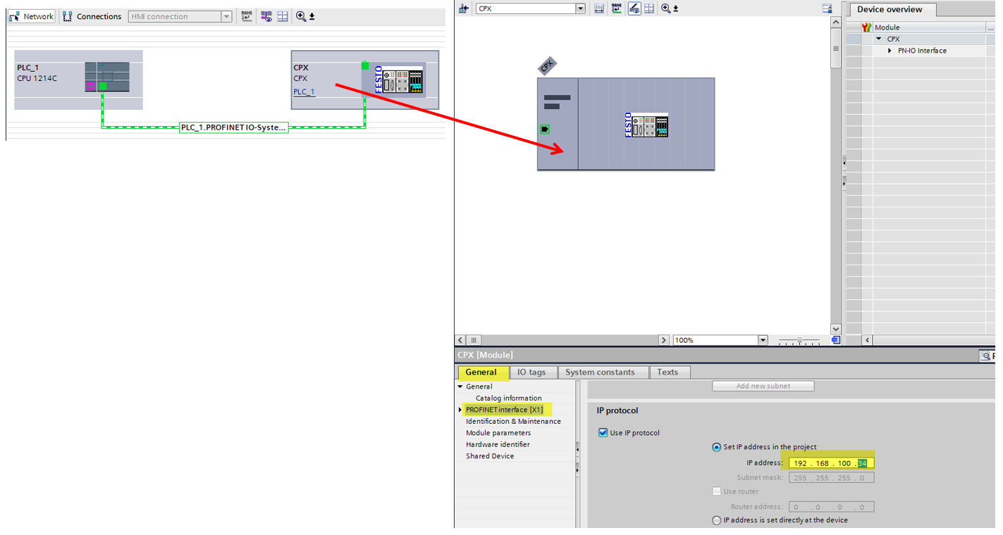
- Click the blue “Not assigned” text and select the PLC ProfiNet interface.
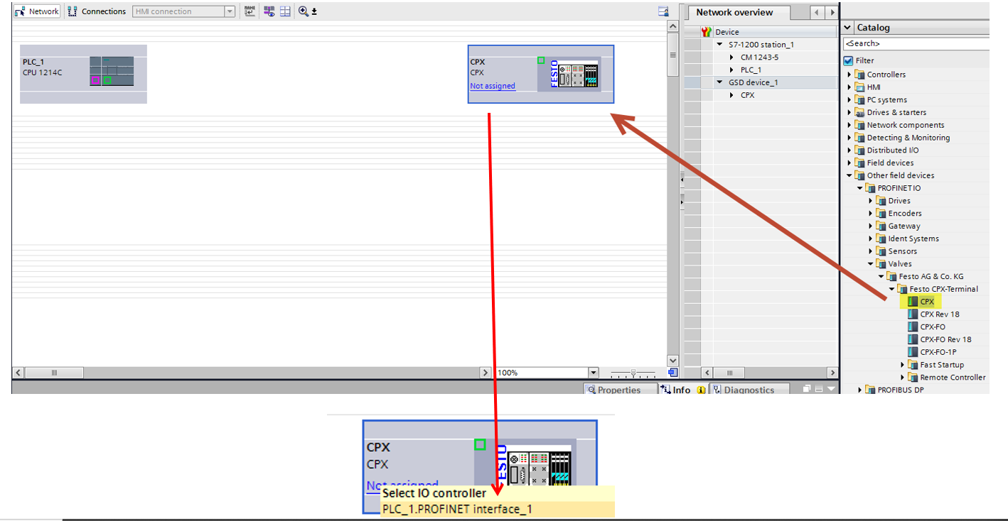
• Notice the Profinet network now linked between the PLC and the CPX. Double-click the CPX, then go to the General tab for ProfiNet interface (X1) information. Set your IP address for the FB34 field bus node.
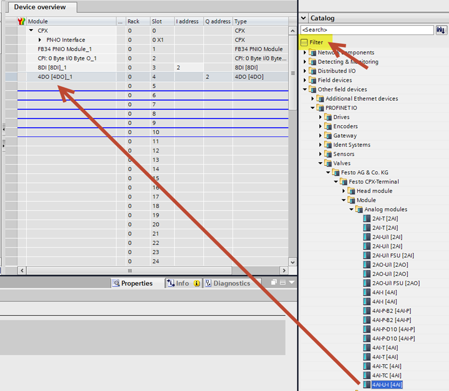
• Add Valve Terminal modules to your CPX. Find the correct module info in the Catalog tree, then drag and drop into the proper slots in the CPX. Note: Be sure the Filter button is unchecked!!! Hint: The slot outlines will turn blue if acceptable modules are chosen.
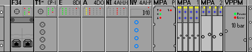
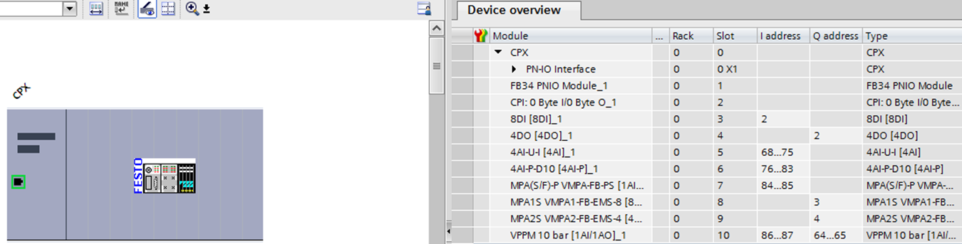
• Review your added modules and check that they match actual CPX in both position and description.
Download the PLC & CPX Configuration
- Highlight the CPX, then click “Compile”.
- Return to “Devices & networks” view.
- Save Project.
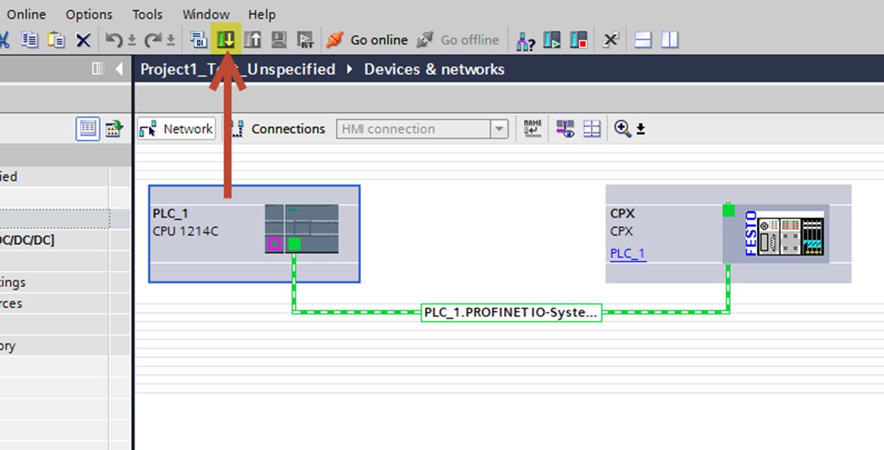
- Highlight the PLC in the network view, then Download the project to the PLC.
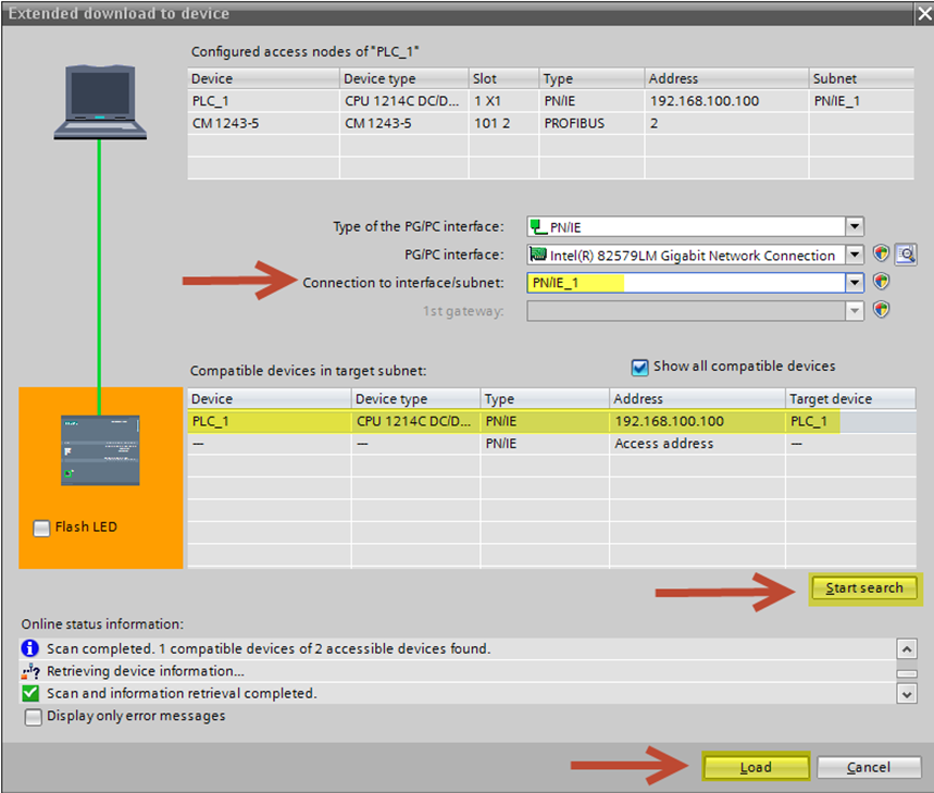
- Within the Extended download to device window, select PN/IE_1 for your Connection to interface.
- Click “Start Search”.
- When the PLC has been found, click “Load”.
Go Online With the Project
- Within the Load preview window, select “Stop all” in the Stop modules Target.
- Click “Load”.
- Click “Finish”.
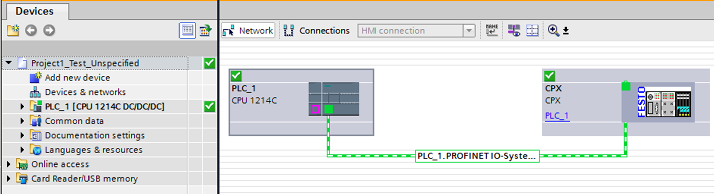
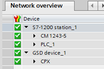
- Select the PLC, then click “Go online”. If all configurations have been completed correctly, you will see the following green check marks.
- Save Project.
Creating PLC tags
- Go Offline with your project.
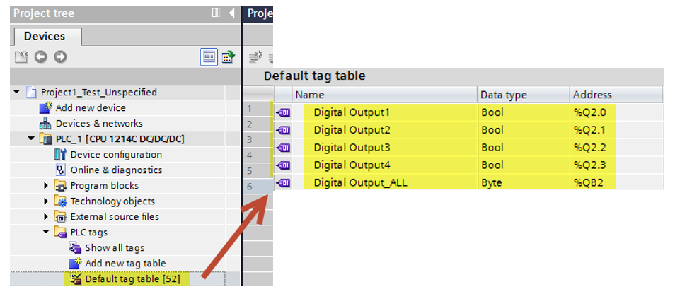
- In LH Project tree, open PLC and go to PLC tags. Double-click Default tag table.
- Assign your required tags according to how you would like them. Refer back to your CPX Device Overview for assigned addresses.
- Tags can be entered individually as bits or whole Byte format (other formats also selectable). This is your choice.
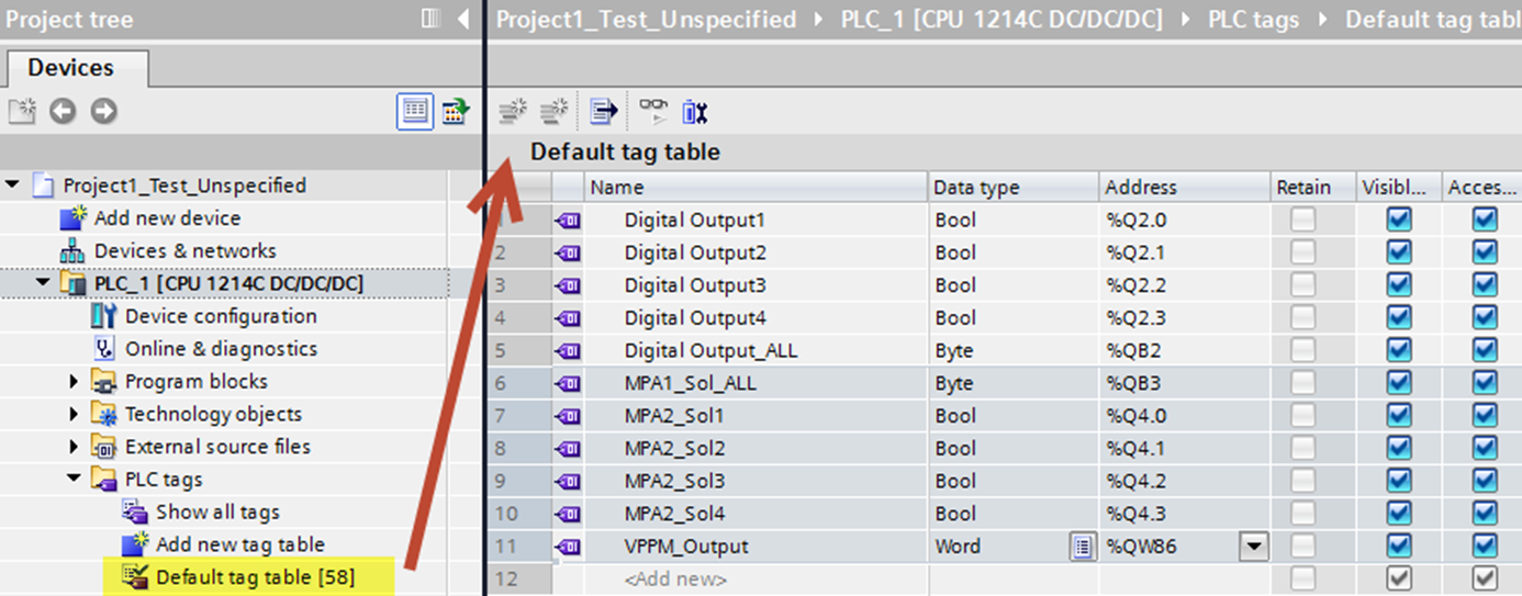
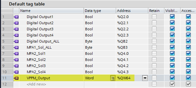
• Continue adding tags and configure the data type and address according to your needs. Notice the VPPM data type is set up as %QW which represents Output Word.
Creating Force Table
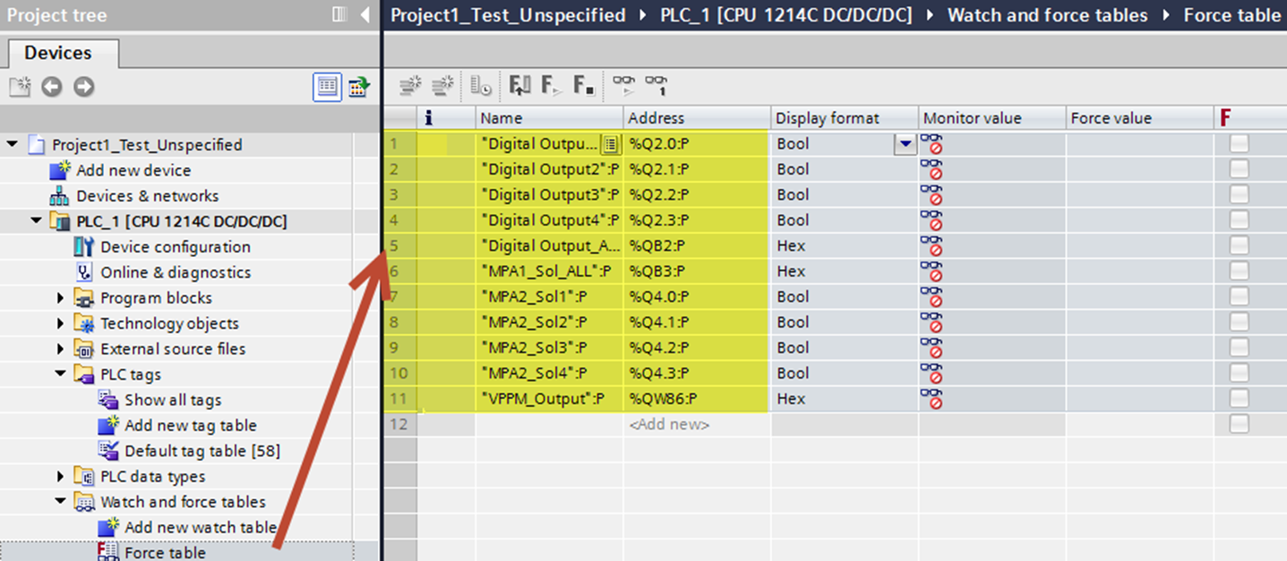
- In LH Siemens Project tree, click Watch and force table. Double-click the Force table.
- Cut and paste your data created from the Default tag table into your Force table. If you prefer to manually type them into the Force table, that will also work. The project will reference your address and data type from the Tag table.
- When the Force table is complete, click “Compile”. Then Download to Device, then Go Online. It’s time for testing!
- Save Project.
Forcing Outputs Test (Digital)
- Make sure you are Online and the CPU is in Run mode.
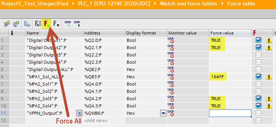
- Go to the Force table. Change the Force value to outputs (from 0 to 1 or False to True). Click “Force All” button. Notice that bits change from 0 to 1 or True to False where Hexidecimal is shown for Outputs set up in byte format.
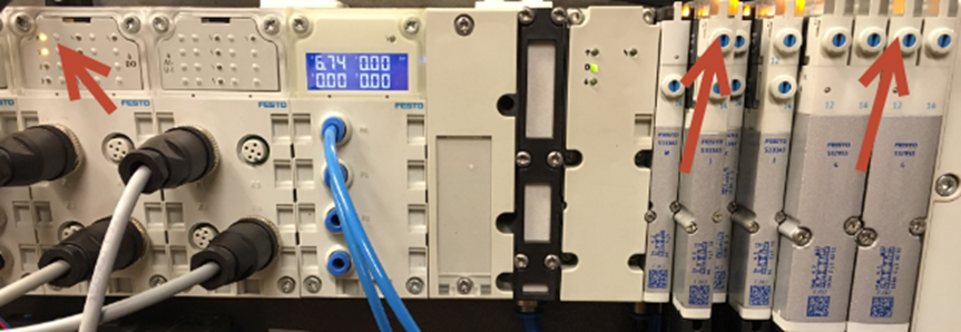
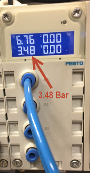
- Confirm that your forced outputs work with your status LEDs on the CPX (shown below).
Forcing Outputs Test (Digital)
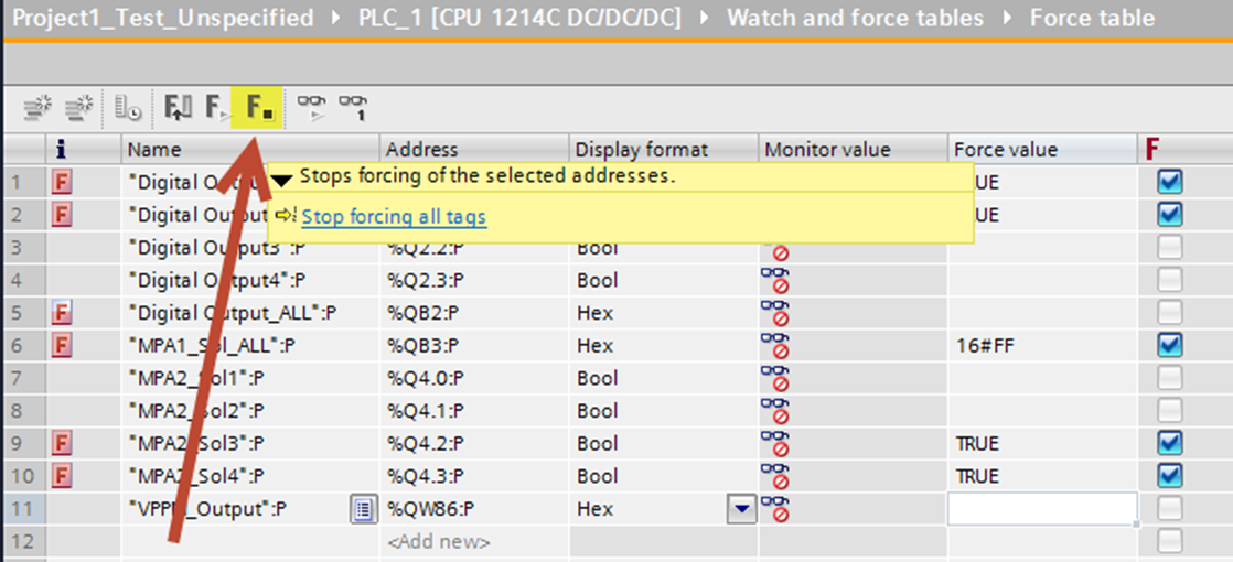
- To turn forces off, click “Stop Forcing” button.
- Manually change all Force values to False or Zero if needed.
Forcing VPPM Outputs Test (Analog)
• Double-click on the Default tag table to see that your VPPM_Output is set to “Word” for Data type. Also notice that the Address is %QW64, which is the first byte of the output address in the CPX (64 & 65).
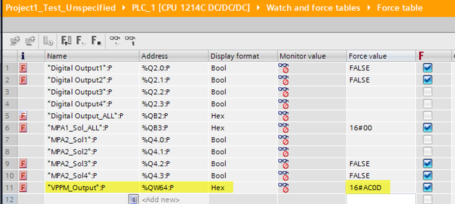
• Double-click the Force table. Notice the VPPM_Output is shown in Display format as “Hex”. The force value is shown as 16#0000.
For example, if desired pressure is 3500 mbar, the calculated Decimal to Hex conversion is shown as: DAC
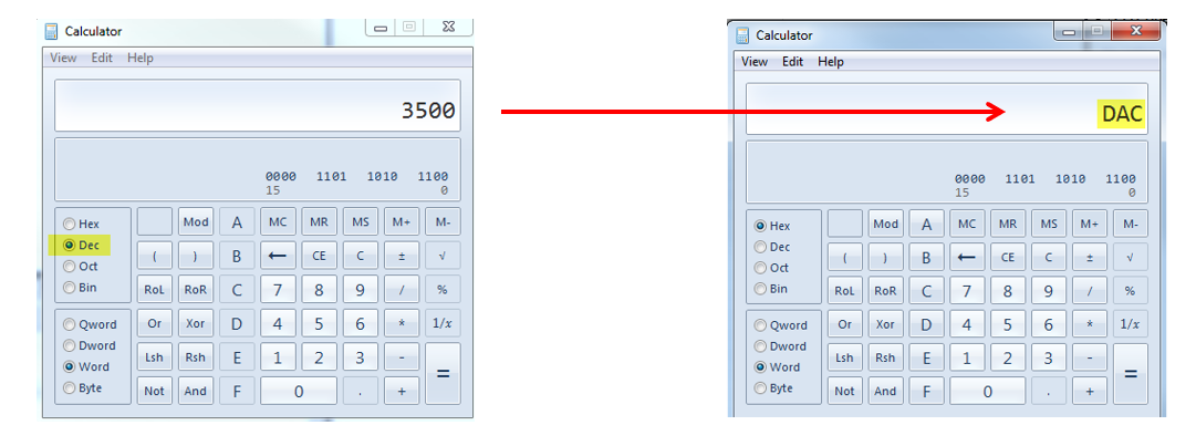
• The format for Siemens will read the low byte data first, then the high byte, so you must reverse these values and input them into the Force Value table.
For 3500 mbar = DAC or 0DAC, reversed it should be input as 16#AC0D
Commissioning with Siemens TIA Portal – Primary Setup Tool
- A helpful Siemens utility called Primary Setup tool is also available to scan, verify and modify network address and node name data.
- If bus faults occur, verify communication by pinging the address of each using the PC command prompt.
Author: Sean Bevis
Festo USA – Automation Technical Engineer
www.festo.com