Quick Start Guide Siemens TIA Portal / Festo CPX-FB34/44 Commissioning

The purpose of this post is to provide a workflow and instructions needed to commission CPX-FB34/44 with Siemens, S7-1200 Series Modular PLC. This document applies to TIA Portal V16 Update 4. These instructions include manual configuration of Siemens and Festo hardware components.

Preparation: Modular PLCs -S7-1200 Hardware Configuration
Festo Valve Terminal Configuration and Diagnostics Setup
Preparation: Festo Software Downloads
- Locate and install Festo Maintenance Tool software
- Locate and install Festo Field Device Tool software
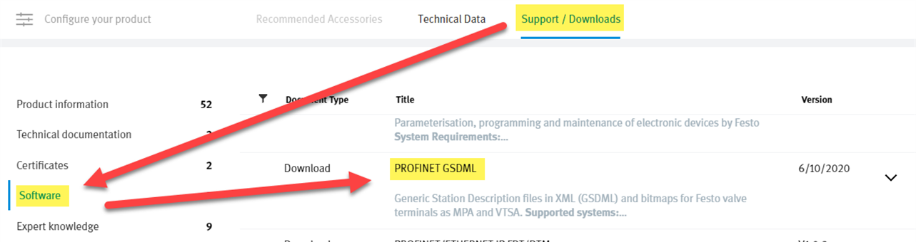
- Locate and install CPX/Profinet GSDML files
FMT: Version Update 21 Released 09.07.2021
FFT: Version 2.10.2.36790 Released 11/16/2020
CPX/Profinet GSDML files: Version 2.34 Released 10/06/2020
Website Link: Support/Downloads – Software Tab
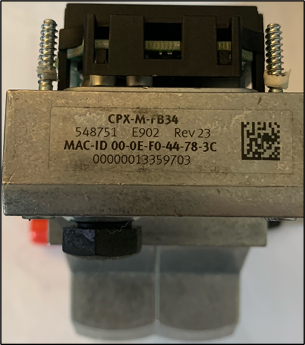
Bus node CPX-M-FB34 | Festo USA
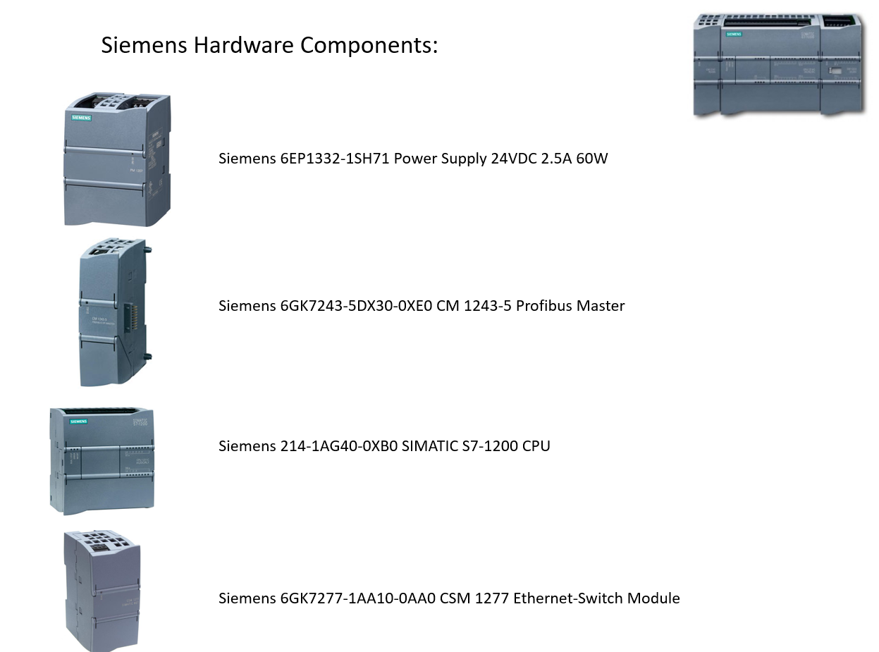
Preparation: Additional Hardware With Festo CPX, Siemens Controller

Commissioning With Siemens TIA Portal: Starting Project
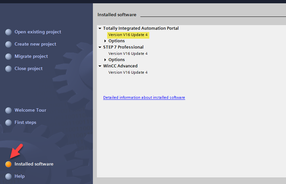
- Start TIA Portal V16, Update 4
Search – V16 – ProductSupport', 'ExampleOfUse', 'Catalog', 'Certificate', 'Characteristic', 'Downlo… – Industry Support Siemens
Application Information
This document will demonstrate the following:
- Show compatibility of FB44 with existing FB34 project by performing a bus node swap.
- Set up FB44 project and demonstrate the new functions of the bus node.
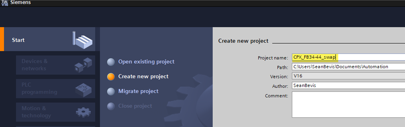
Commissioning With Siemens TIA Portal: Create Project
- Create New Project.
- Select Create after entering project name.
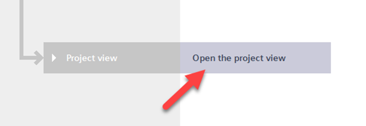
- Select Open the project view.
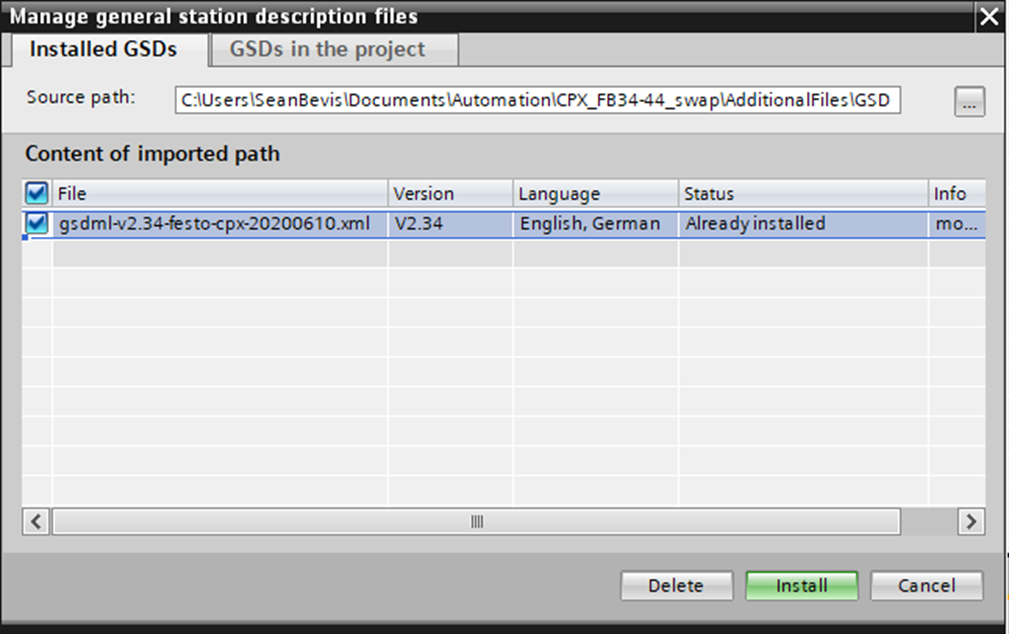
Installation of GSD files for Festo Library
- Navigate to Menu Command for Options > Manage General Station Description Files (GSD).
- Navigate to the directory containing the GSDML file. Please extract contents first.
- Select the GSDML file by checking the box.
- Install.
Commissioning with Siemens TIA Portal: Configure the CPU
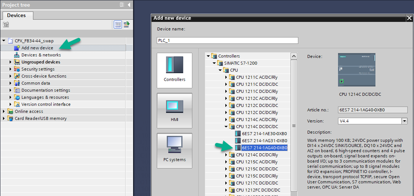
- In the Project tree, click “Add new device”.
- For this example, select CPU 1214C DC/DC/DC. Expand the list and select 6ES7 214-1AG40-0XB0 (V4.4).
- Click “OK” to add the CPU.
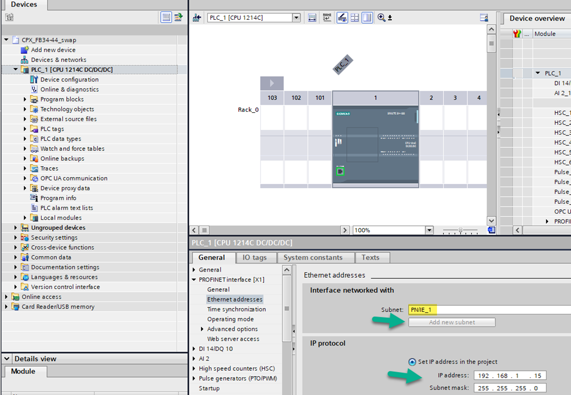
Configure Siemens CPU
- Click “Add new subnet” within the General parameters tab and accept PN/IE_1.
- Enter the IP address and Subnet mask for the CPU.
- Save Project.
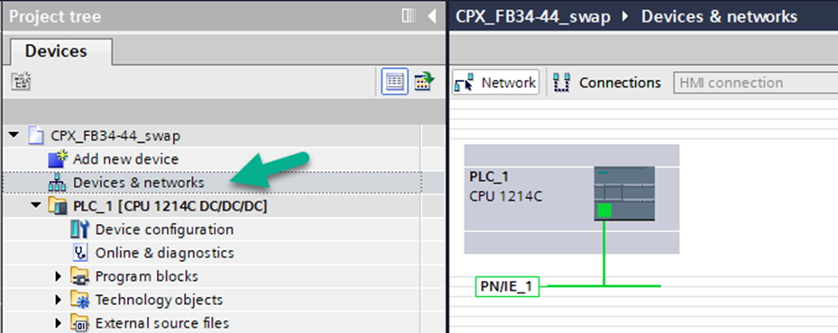
Add Festo CPX Terminal
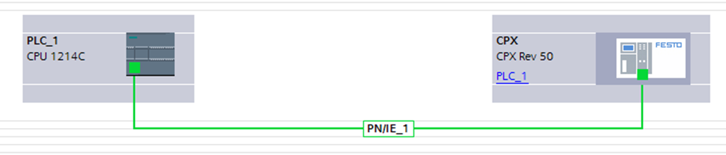
• In the Project tree, double-click “Devices & networks”. You should see your CPU with PN/IE_1 assigned.
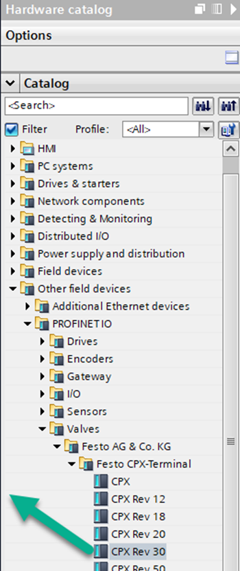
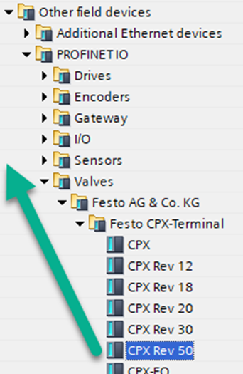
- In the Hardware catalog, locate CPX Rev 30 by expanding the products.
- Drag and drop CPX Rev 30 into the Network space to the right of the CPU.
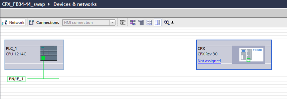
Connect Network of CPU and Festo CPX Terminal
• Using your cursor, grab the end of PLC PN/IE_1 and drag it to the CPX.
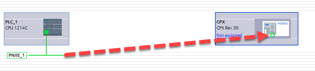
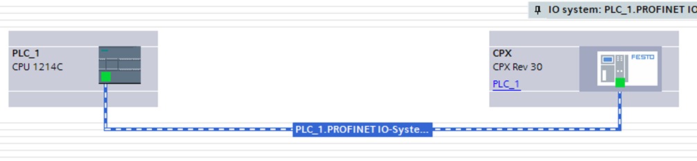
- Now the Profinet communication network is connected between devices.
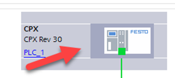
Hardware Configuration: Add CPX Modules
- Double-click on the CPX from the Network View.
- Using the Catalog, drag and drop CPX modules accordingly.
- Check for PN/IE_1 Subnet and input IP address information.
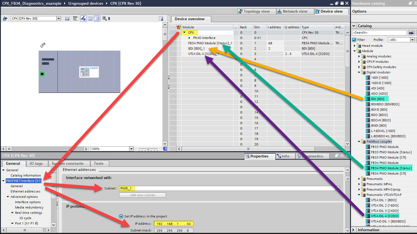
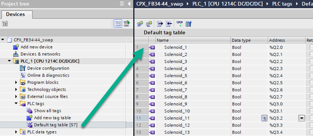
Review and Setup of I/O Tags
• Review the addressing for each module.
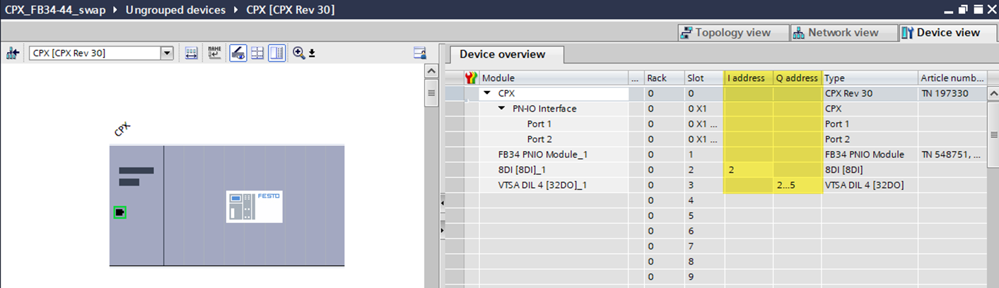
- Add any tags you feel are needed.
Create Watch/Force Table
• Click “Add new watch table”, then enter the tag name you created. Drag the lower right corner to auto-copy.
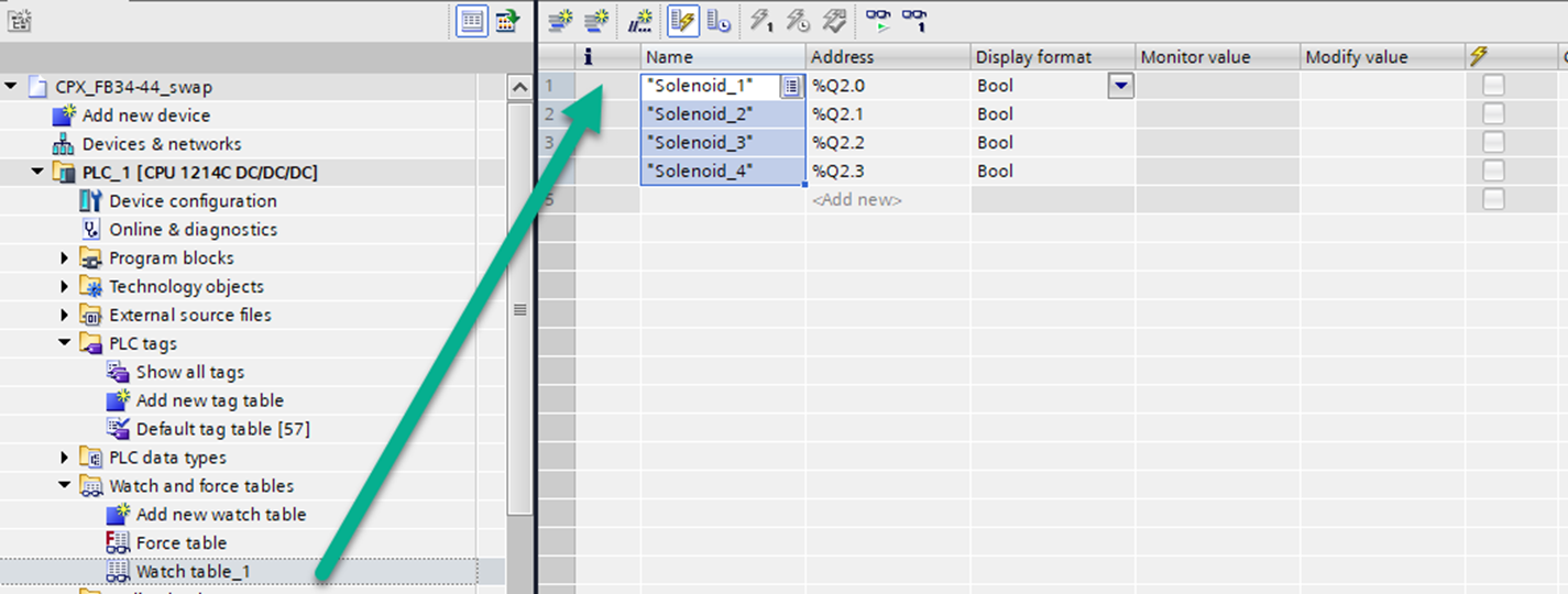
- Save Project.
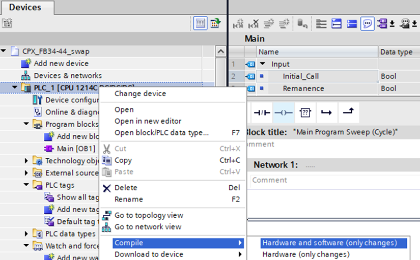
- Right-click PLC_1 and select “Compile>Hardware and software (only changes)”.
Compile Hardware and Software Download
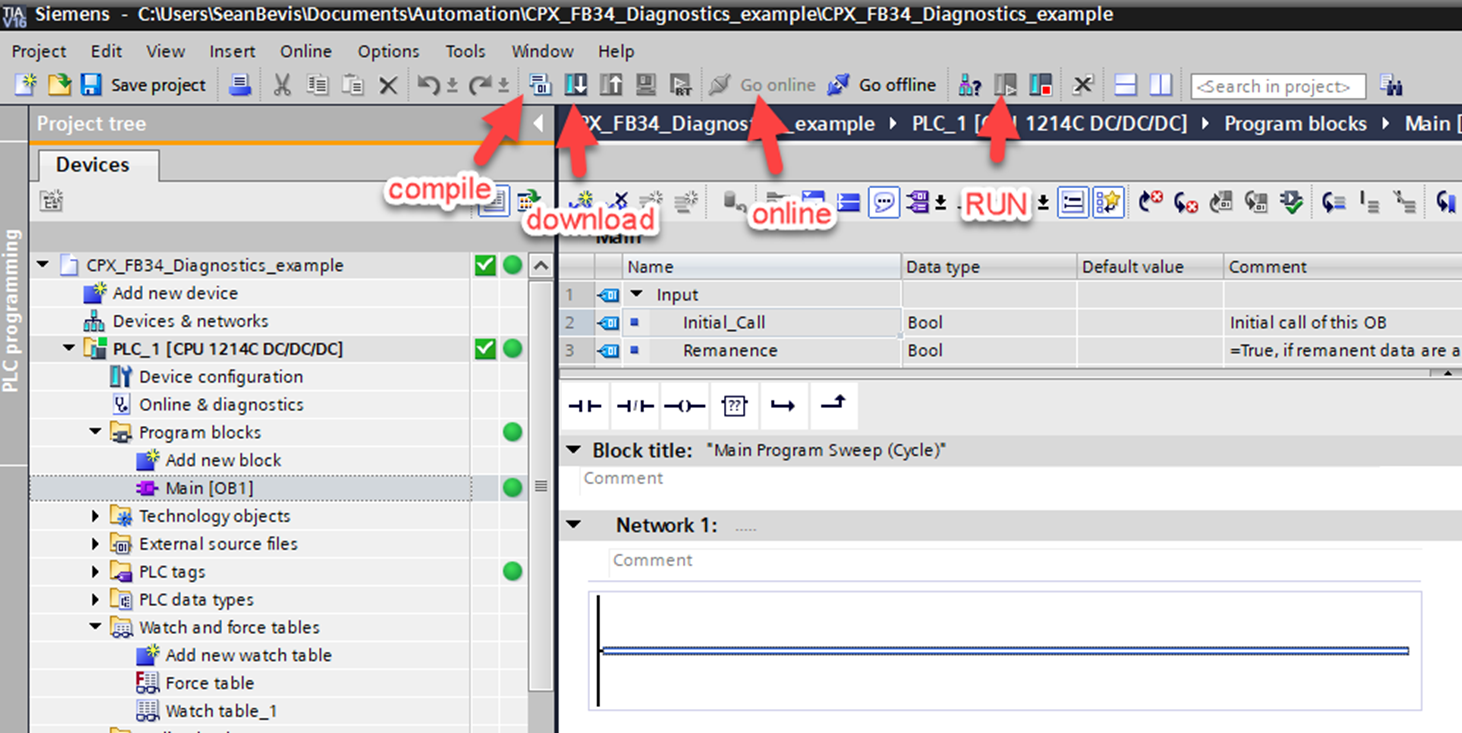
- Compile hardware and software.
- You should see no errors. Some warnings are normal and can be resolved.
- Download Project, Go Online, make sure PLC is in RUN mode.
Confirmation of I/O Signals PLC to Festo CPX Terminal
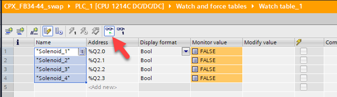
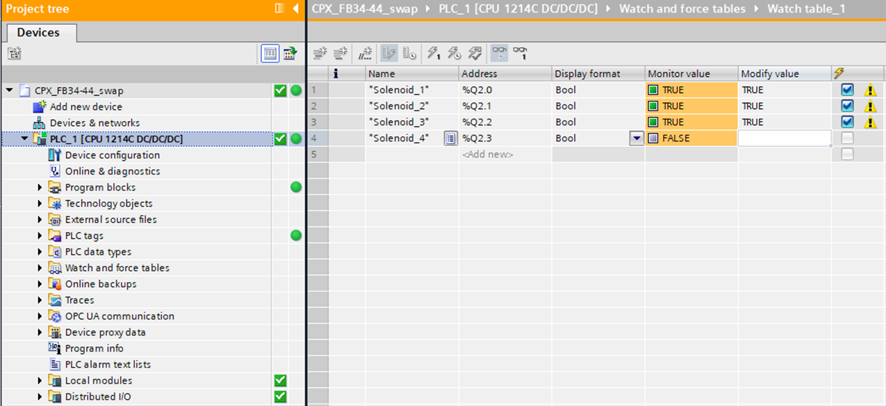
• Open the Watch Table and click the “Monitor All” glasses. Notice the Monitor value shows state.
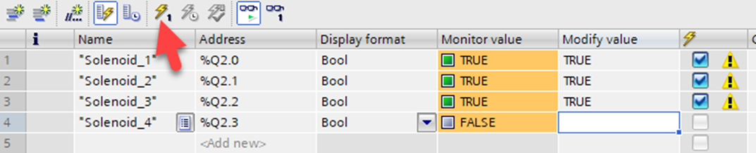
- Change a value by typing a “1” into the Modify value box.
- Select the “Modify All” button to force the value.
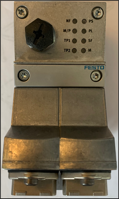
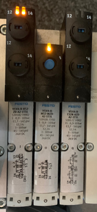
- Confirm the solenoid LED turns ON.
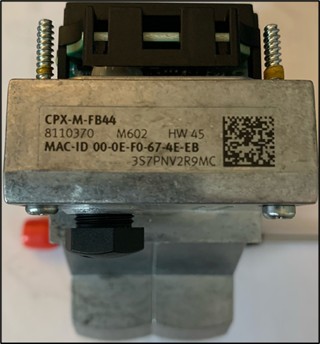
Swap in FB44 Profinet Node
- Go Offline with the PLC, then power OFF the CPX.
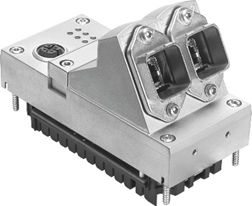
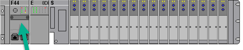
- Remove the FB34 bus node using T10 torx. Replace with FB44 bus node, tighten screws.
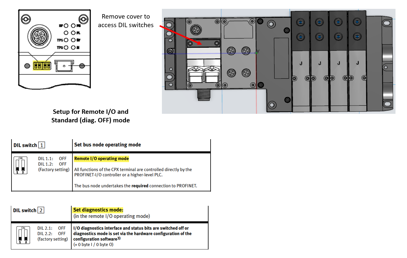
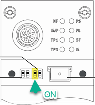
- Set the DIL switches same as FB34, reconnect network cable then power ON the CPX.
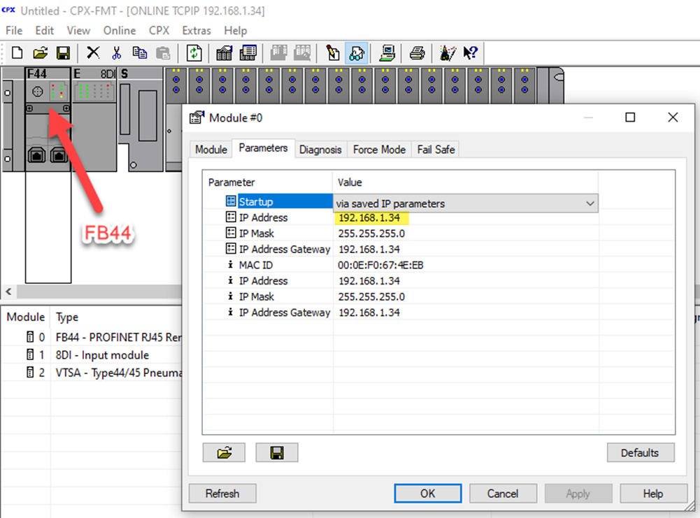
- Use Festo Maintenance Tool to confirm IP address settings, then close FMT.
Test Swap-In Feature of FB44
- Go Online with PLC and confirm no errors.
- System should accept the FB44 bus node even though the project is set up for FB34.
- Re-test forcing of solenoid valves to confirm functionality.

Commissioning of FB44 Profinet Node
- Complete the steps to create a new project using the same PLC.
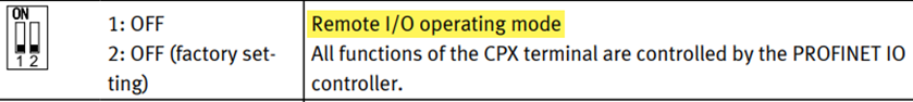
- Set the FB44 DIL switches to Remote I/O and I/O Diagnostics interface ON.
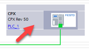
- When adding the CPX Terminal to the Network view, use Rev.50.
- Drag and drop PN/IE_1 network to CPX.

Hardware Configuration: Add CPX Modules
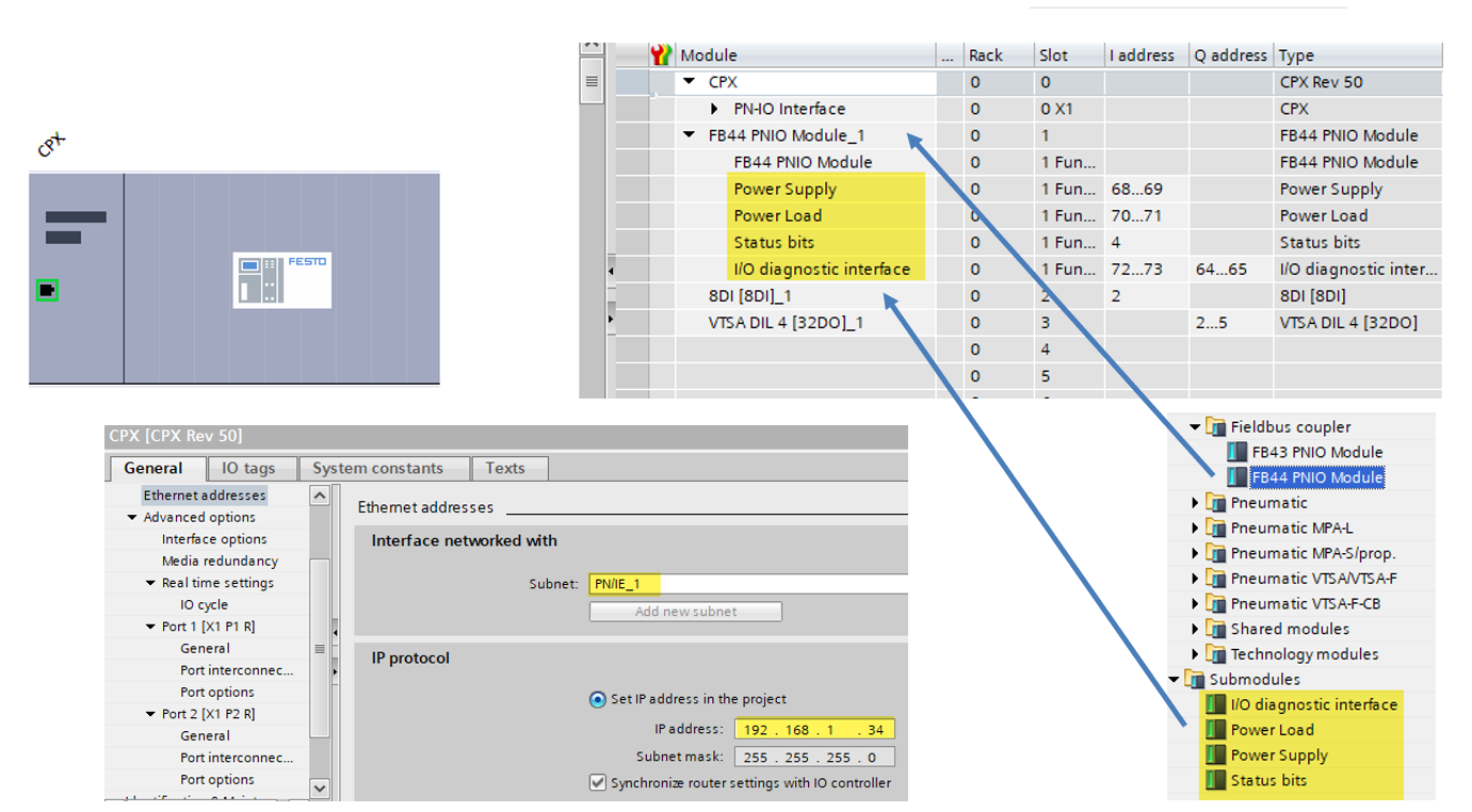
- Double-click on the CPX from the Network View.
- Using the Hardware Catalog, drag and drop CPX modules accordingly. Notice (4) new features of the FB44 bus node to add.
- Check for PN/IE_1 Subnet and input IP address information.
Compile Hardware and Software Download
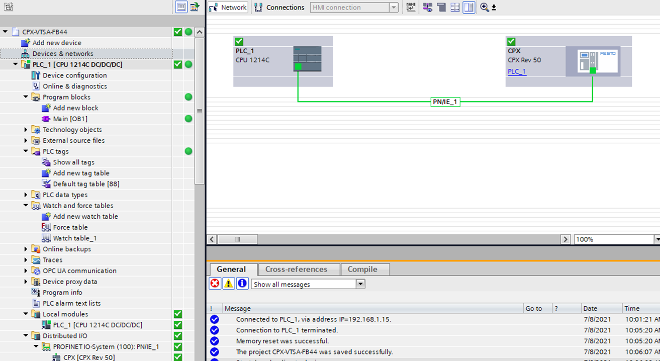
- Compile hardware and software, then download Project and go Online.
- You should see no errors. Some warnings are normal and can be resolved.
Note: If no errors on FB44 are active but the project has errors, disconnect the network cable from the CPX-FB44 and cycle power to the PLC. Go online with the PLC without CPX being connected, then plug the network cable back in.
Review of FB44 I/O Diagnostics Interface
- The new FB43/44/45 Profinet bus nodes have four new features:
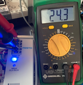
1. Voltage Measurement: ability to monitor PS & PL supply voltage.*
2. MRPD (Media Redundancy for Planned Duplication): allow for a Ring Topology.
3. NTP Time Sync: allow the CPX to see real-time clock values.
4. S2 System Redundancy: ability to use a redundant PLC for process stability
*Note: This document will only review the Voltage Measurement feature.
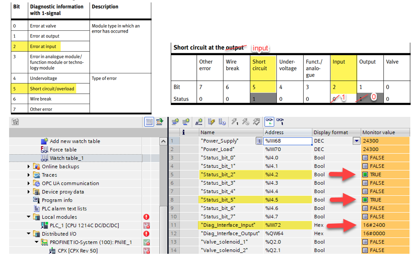
- In the Watch Table, notice the Power Supply (PS) and Power Load (PL) variables listed as an Input Word (%IW). These are monitoring the DC input voltage and can be seen by the PLC in real time.
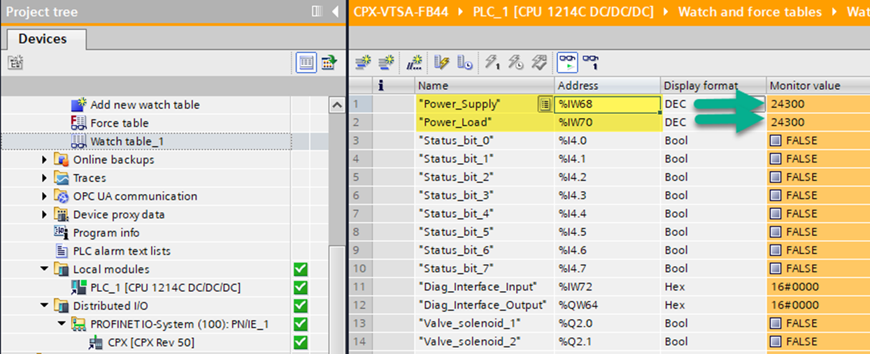
The error shown below was created by a short in the CPX Input module.
- Review Status bits: bit 2 & bit 5 ON indicate Short Circuit on Input (0010_0100).
- Review of Diagnostics Interface: 16#2400.
Commissioning With Siemens TIA Portal: Primary Setup Tool
- A helpful Siemens utility called Primary Setup tool is also available to scan, verify and modify network address and node name data.
- If bus faults occur, verify communication by pinging the address of each using the PC command prompt.
Author: Sean Bevis
Festo USA – Automation Technical Engineer
www.festo.com