How to Make Efficient, Error-Free Process Adjustments — Part II

Following up on our last blog post, we turn now to the remaining three steps in our five-step process to avoid unwanted device tampering. These three steps — implementing sensors, maintaining centerlining and utilizing visual indicators — can help you ensure machine process adjustments are always effective and correct.
Step 3. Implement Sensors for Condition Monitoring
Your third step in the process — after eliminating unnecessary process adjustments and using automation to eliminate human error — is to monitor and detect the status of processes that may be affected by any process adjustments. Examples include:
- Differential pressure monitoring solutions that can help you determine when you may need to replace your filters.
- Pressure sensors and switches that can communicate with the PLC, verifying if a process is within the desired pressure range.
- Flow sensors that monitor the amount of consumed air, indicating if a process is performing as expected.
Step 4. Maintain Centerlining
Of course, automatic process adjustments are not always possible. If you do need to make a manual adjustment, we recommend using a numerical scale to ensure the adjustments are consistent. For example, look for flow control components with position markings or digital flow meters: the GRLASA- one-way flow control valve includes a labeled adjustment ring, while SPAN, SFAB and SFAM flow sensors feature an integrated display, ensuring you achieve your desired flow rate.
Step 5. Take Advantage of Red and Green Visual Indicators
Your last and final step is to use pneumatic components with red and green indicators. These features offer a quick and easy way to validate when processes are performing as expected.
For example, MA-RG pressure gauges include an adjustable red and green range, providing an extra level of safety when monitoring your compressed air usage. Units include two red segments above the pressure gauge scale, as well as a printed green segment. Thanks to this colored demarcation, you can immediately identify when the pressure is or isn’t in its permitted tolerance range.
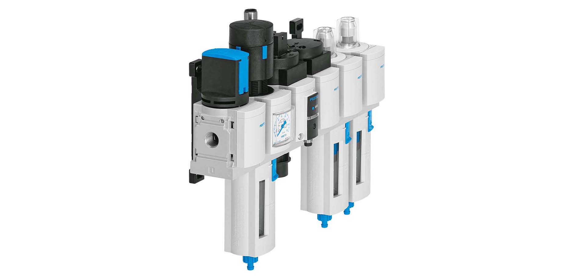
Similarly, MS Series components, which include pressure regulators, ON/OFF valves, soft-start valves, pressure sensors and flow sensors, feature an integrated red and green scale that displays the output pressure. SFAM flow sensors, for example, feature an illuminating red and green display that indicates when the flow is out of the desired range.
To learn more about reducing error-prone or inefficient process adjustments, download our white paper.
